Газонокосилки Stiga Combi 36 - инструкция пользователя по применению, эксплуатации и установке на русском языке. Мы надеемся, она поможет вам решить возникшие у вас вопросы при эксплуатации техники.
Если остались вопросы, задайте их в комментариях после инструкции.
"Загружаем инструкцию", означает, что нужно подождать пока файл загрузится и можно будет его читать онлайн. Некоторые инструкции очень большие и время их появления зависит от вашей скорости интернета.


4
on the last page of the manual.
The example of the Declaration of Conformity is provided
on the penultimate page of the owner’s manual.
Do not dispose of electrical equipment with house
-
hold waste material. In observance of European
Directive 2012/19/EU on electrical and electronic
equipment waste and its implementation in accord
-
ance with national regulations, electrical equipment that
has reached the end of its product life must be collected
separately and recycled in an ecologically compatible way.
If electrical equipment is disposed of in dumps or in land
-
fills, hazardous substances can leak into the groundwater
and contaminate the food chain, damaging your health and
well-being. For further information on the disposal of this
product, contact your dealer or a domestic waste collection
service.
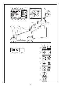
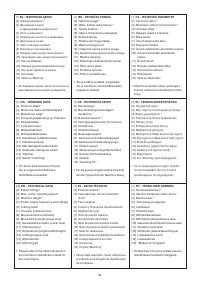
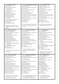
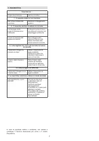
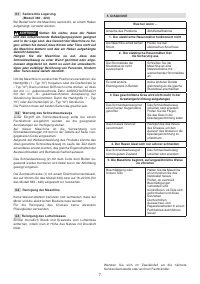
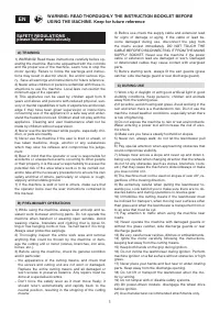
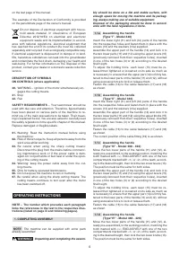
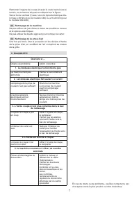
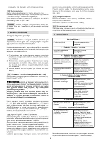
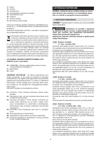
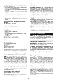
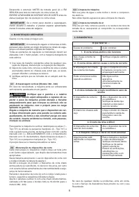
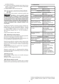
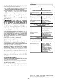
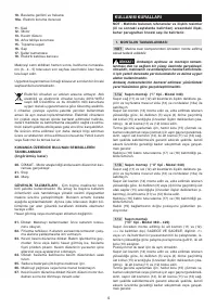
DESCRIPTION OF SYMBOLS
ON CONTROLS (where applicable)
20.
WARNING – Ignition of the motor simultaneously en
-
gages the cutting means.
21.
Stop
22.
Run
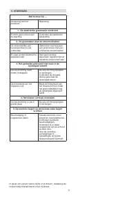
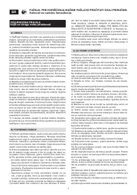
SAFETY REQUIREMENTS
– Your lawnmower should be
used with due care and attention. Therefore, figured labels
have been placed on various parts of the machine to re
-
mind you of the main precautions to be taken. Their mean
-
ing is explained below. You are also asked to carefully read
the safety regulations in the specific chapter of this manual.
Replace damaged or illegible labels.
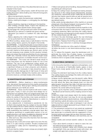
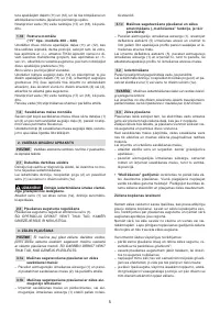
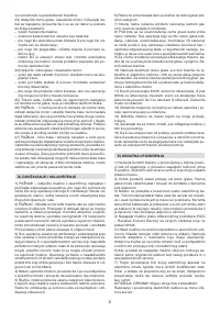
61.
Warning: Read the instruction manual before using
the machine.
62.
Risk of thrown objects. Keep all persons away from the
work area whilst working.
63.
Be careful when using the sharp cutting means:
Disconnect the plug from the mains before commenc
-
ing maintenance work or if the power cable is dam
-
aged. Do not put hands or feet near or under the open-
ing of the cutting means
64.
Warning: keep the power cable away from the cut
-
ting means.
65.
Only for battery-operated lawnmowers.
66.
Do not expose the machine to rain or humidity.
67.
Be careful when using the sharp cutting means: The
cutting means continues to turn even after the motor
has been switched off.
OPERATING INSTRUCTIONS
NOTE – The number which precedes each paragraph
links the references in the text to the respective illus
-
trations (listed on page iii and following pages).
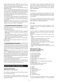
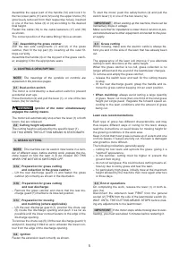
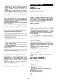
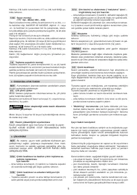
1. COMPLETING ASSEMBLY
NOTE
The machine can be supplied with some parts
already assembled.
WARNING!
Unpacking and completing the assem-
bly should be done on a flat and stable surface, with
enough space for moving the machine and its packag-
ing, always making use of suitable equipment.
Disposal of the packaging should be done in accord-
ance with the local regulations in force.
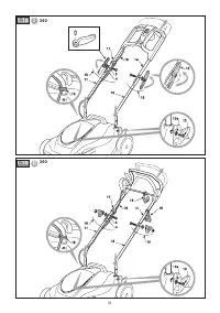
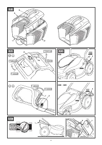
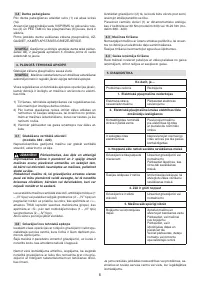
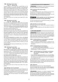
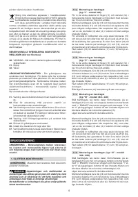
1.1a Assembling the handle
(Type“I” - Model 340)
Insert the lower right (11) and left (12) parts of the handle
into the respective holes and fasten them in place with the
screws (13) and the washers (13a) supplied.
Assemble the upper part of the handle (14) and lock it to
the two lower parts (11) and (12) using the upper levers (15)
(previously removed from their respective holes), inserted
in one of the two holes (3) or (4) according to the desired
final height.
To adjust the holding force, each lever (15) must be re
-
leased then tightened or loosened on its axle as much as
is necessary to ensure that the upper part (14) is firmly fas
-
tened to the lower parts of the handle (11) and (12), without
using excessive force to lock or release them.
Fasten the cable (16) to the cable fasteners (17) and (18)
as shown.
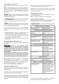
1.1b Assembling the handle
(Type“Il” - Model 340)
Insert the lower right (11) and left (12) parts of the handle
into the respective holes and fasten them in place with the
screws (13) and the washers (13a) supplied.
Assemble the upper part of the handle (14) and lock it to
the two lower parts (11) and (12) using the upper knobs (15)
(previously removed from their respective holes), inserted
in one of the two holes (3) or (4) according to the desired
final height.
Fasten the cable (16) to the cable fasteners (17) and (18)
as shown.
The correct position of the cable fitting (19) is as shown.
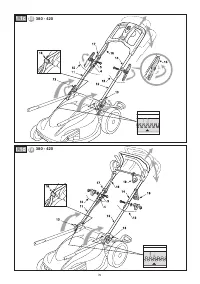
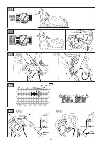
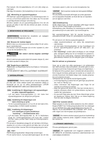
1.1c Assembling the handle
(Type“Ill” - Model 380 - 420)
Move the two lower parts of the handle (11) and (12), al
-
ready pre-assembled, to the working position, matching the
tooth marked with «>» EXCLUSIVELY with one of the two
compartments marked with «1» or «2» of the teeth, accord
-
ing to the desired height, then lock the two lower levers (13).
The position must be the same for both sides.
Assemble the upper part of the handle (14) and lock it to
the two lower parts (11) and (12) using the upper levers (15)
(previously removed from their respective holes), inserted
in one of the two holes (3) or (4) according to the desired
final height.
To adjust the holding force, each lever (15) must be re
-
leased then tightened or loosened on its axle as much as
is necessary to ensure that the upper part (14) is firmly fas
-
tened to the lower parts of the handle (11) and (12), without
using excessive force to lock or release them.
Fasten the cable (16) to the cable fasteners (17) and (18)
as shown.
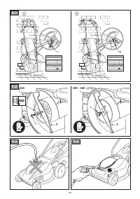
1.1d Assembling the handle
(Type“IV” - Model 380 - 420)
Move the two lower parts of the handle (11) and (12), al
-
ready pre-assembled, to the working position, matching the
tooth marked with «>» EXCLUSIVELY with one of the two
compartments marked with «1» or «2» of the teeth, accord
-
ing to the desired height, then lock the two lower knobs (13).
The position must be the same for both sides.
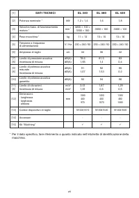
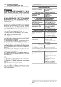
Характеристики

Остались вопросы?Не нашли свой ответ в руководстве или возникли другие проблемы? Задайте свой вопрос в форме ниже с подробным описанием вашей ситуации, чтобы другие люди и специалисты смогли дать на него ответ. Если вы знаете как решить проблему другого человека, пожалуйста, подскажите ему :)

