
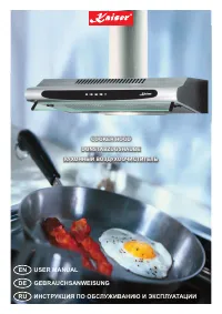
Вытяжки Kaiser A 600 IX - инструкция пользователя по применению, эксплуатации и установке на русском языке. Мы надеемся, она поможет вам решить возникшие у вас вопросы при эксплуатации техники.
Если остались вопросы, задайте их в комментариях после инструкции.
"Загружаем инструкцию", означает, что нужно подождать пока файл загрузится и можно будет его читать онлайн. Некоторые инструкции очень большие и время их появления зависит от вашей скорости интернета.
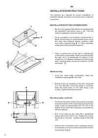
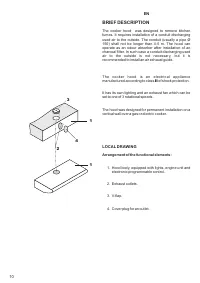
INSTALLATION INSTRUCTIONS
Two persons are required for proper installation. A
qualified installer should be commissioned to make the
connection.
INSTALLATION OF THE COOKER HOOD
• Remove the grease filter before proceeding with
the assembly instructions (see p. 20). This will
make the appliance easier to handle.
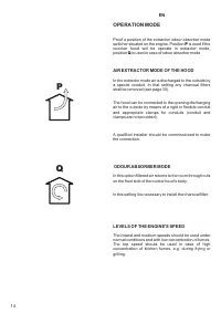
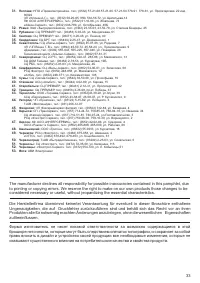
• For an operation in air extractor mode set the V-
flap
1
concerning your requirements to the one of
two (top/ rear) exhaust outlets, another outlet
cove with a special plug
2
. In odour absorber
mode both outlets should be opened.
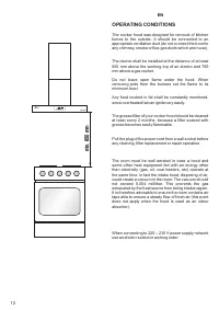
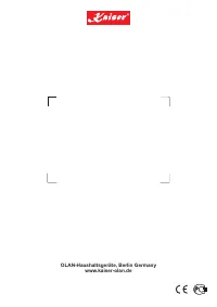
• Trace a vertical line on the wall to indicate the
centre of the cooker plate. Place a hood body
3
to
the wall, set it symmetrically in relation to the
central line, the distance between its bottom side
and a heating plate should be minimum of 650
mm (see p. 12).
Wall mounting
• Level the hood body horizontally. Mark the
installation openings
4
on the wall.
• Drill the holes as indicated on the wall, using drill
of 8 mm diameter. Drive the plugs in and then
hang the hood body on the wall using 2 top
screws. Tighten the bottom screws.
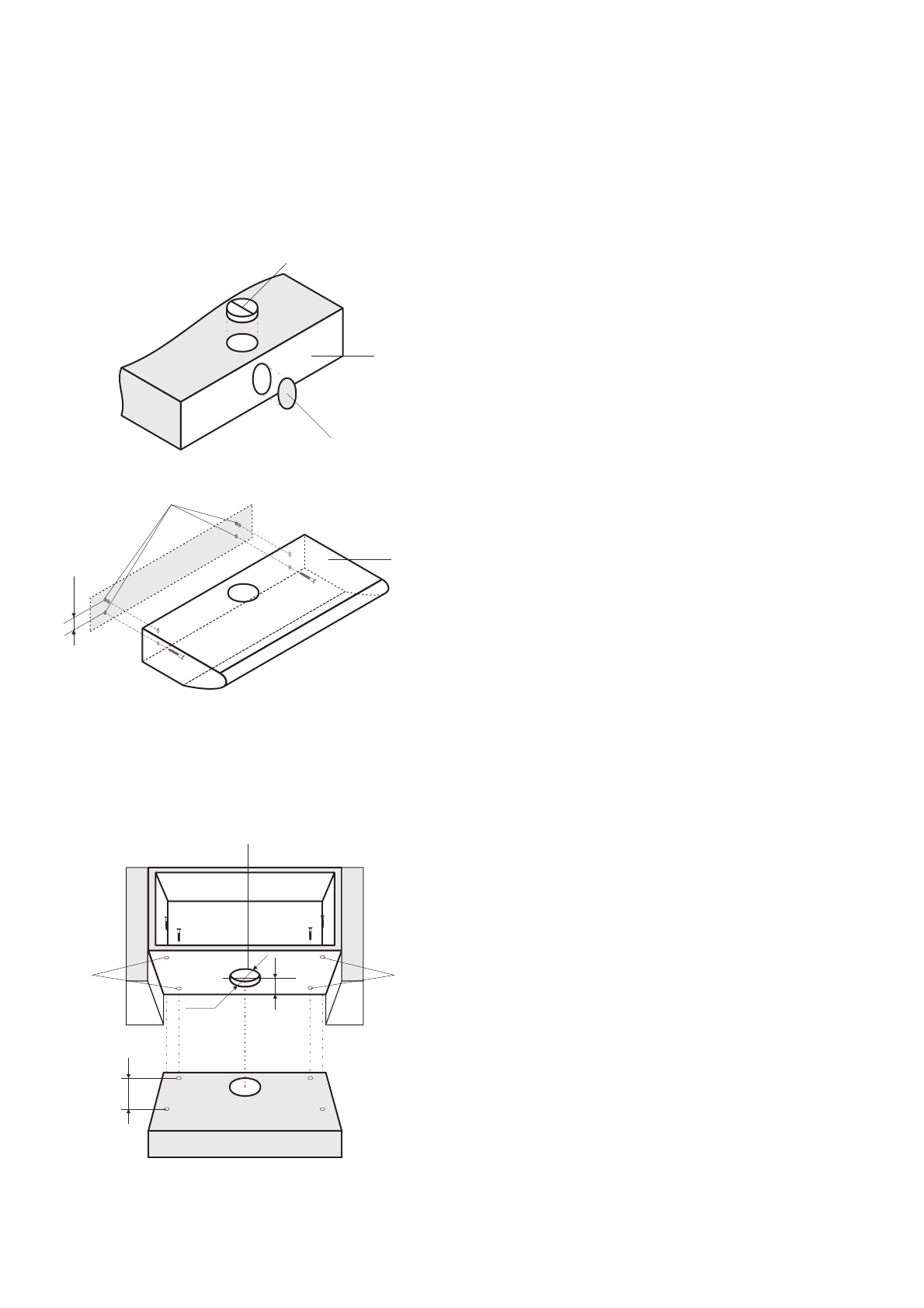
Mounting under a wall unit
• For the air extractor mode of the cooker hood with
a vertical location of the vent conduit using the top
outlet, make an opening
5
of Ø 133 mm in the
bottom of the wall unit in advance in accordance
with the drawing.
• Drill in the wall unit the holes
6
in predefined
places with a drill of Ø 6 mm. Fasten the cooker
hood with a 4 screws, operate inside of the wall
unit.
• If the cooker hood will be use in extractor mode it
is necessary to mount a vent conduit of Ø 125 mm
on the fixed V-flap
1
.
EN
44
85
Ø 133
256
2
3
3
1
4
5
6
6
6
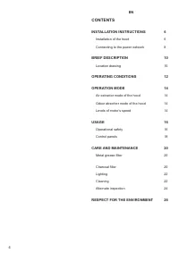
Содержание
- 7 ИНСТРУКЦИЯ ПО МОНТАЖУ; МОНТАЖ ВОЗДУХООЧИСТИТЕЛЯ; Монтаж на стене; FÜR DEN INSTALLATEUR; MONTAGE DER DUNSTABZUGSHAUBE; Montage an der Wand
- 11 КРАТКОЕ ОПИСАНИЕ; ВНЕШНИЙ ВИД; KURZBESCHREIBUNG; GESAMTANSICHT; Anordnung von Funktionsbaugruppen:
- 13 (это условие не требуется, если вытяжное
- 15 РЕЖИМЫ РАБОТЫ; используется, если устройство будет; BETRIEBSARTEN DER ABZUGSHAUBE; ist für Abluftbetrieb und die Stellung
- 17 BENUTZUNG; BENUTZUNGSSICHERHEIT; ИСПОЛЬЗОВАНИЕ; БЕЗОПАСНОСТЬ ЭКСПЛУАТАЦИИ; и угольные фильтры
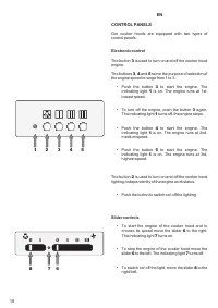
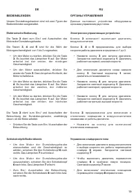
- 19 ОРГАНЫ УПРАВЛЕНИЯ; Электронное управляющее устройство; BEDIENBLENDEN; Elektronische Bedienung
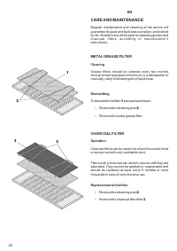
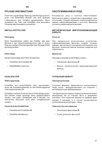
- 21 ОБСЛУЖИВАНИЕ И УХОД; УГОЛЬНЫЙ ФИЛЬТР; соедин н с; PFLEGE UND WARTUNG; METALLFETTFILTER
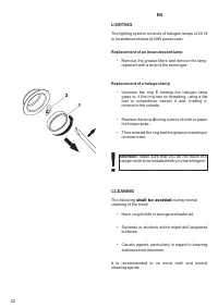
- 23 ОСВЕЩЕНИЕ; галогеновой лампы; ОЧИСТКА; не следует; BELEUCHTUNG; Austausch der Gluhlampe; REINIGUNG; sollen Sie vermeiden
- 25 ПЕРИОДИЧЕСКИЙ ОСМОТР; следует; PERIODISCHE BESICHTIGUNG; ist
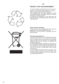
- 27 ОХРАНА ОКРУЖАЮЩЕЙ СРЕДЫ; Утилизация упаковки; UMWELTVERTRÄGLICHKEIT; Verpackungs-Entsorgung
- 28 УСЛОВИЯ ГАРАНТИИ; ГАРАНТИЯ НЕ РАСПРОСТРАНЯЕТСЯ:; Незаземленное оборудование является потенциально опасным.
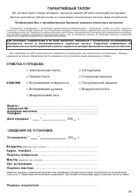
- 29 ГАРАНТИЙНЫЙ ТАЛОН; ОТМЕТКА; ИЗДЕЛИЕ; СВ
Характеристики

Остались вопросы?Не нашли свой ответ в руководстве или возникли другие проблемы? Задайте свой вопрос в форме ниже с подробным описанием вашей ситуации, чтобы другие люди и специалисты смогли дать на него ответ. Если вы знаете как решить проблему другого человека, пожалуйста, подскажите ему :)


