
Вытяжки Falmec Lumina 120 - инструкция пользователя по применению, эксплуатации и установке на русском языке. Мы надеемся, она поможет вам решить возникшие у вас вопросы при эксплуатации техники.
Если остались вопросы, задайте их в комментариях после инструкции.
"Загружаем инструкцию", означает, что нужно подождать пока файл загрузится и можно будет его читать онлайн. Некоторые инструкции очень большие и время их появления зависит от вашей скорости интернета.

31
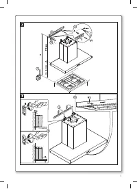
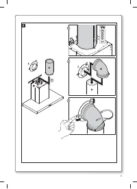
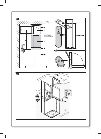
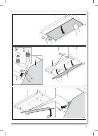
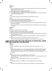
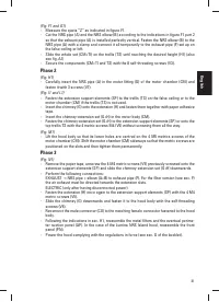
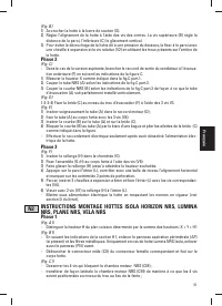
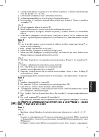
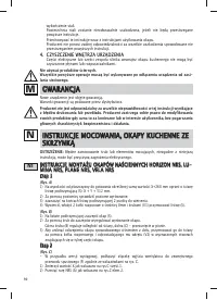
(Fig. F1 and G1)
- Measure the quota “Z” as indicated in figure F1.
- Cut the NRS pipe (A) and the NRS elbow (B) according to the indications in figure F1 part 2
so that the exhaust pipe (A) is installed perfectly vertical. Fasten the NRS elbow (B) to the
NRS pipe (A) with a clamp and connect it all temporarily to the exhaust pipe (F) set up on
the false ceiling or loft.
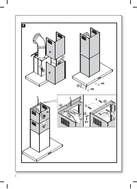
- Slide the whole set (CM+TI) on the trellis (TS) until reaching the desired height (H1) (also
see fig. A1)
- Secure the components (CM+TI and TS) with the 8 self-threading screws (V3).
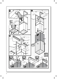
Phase 2
(Fig. H1)
- Carefully insert the NRS pipe (A) in the motor fitting (D) of the motor chamber (CM) and
fasten it with 3 screws (V7).
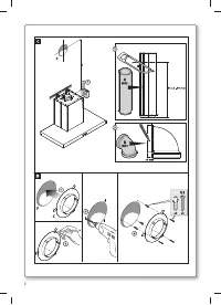
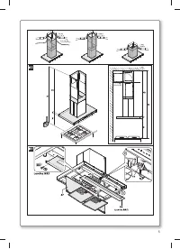
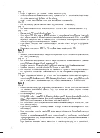
(Fig. I1 and L1)
- Fasten the extension support elements (SP) to the trellis (TS) on the false ceiling or to the
motor chamber (CM) if the trellis (TS) is not used.
- Insert the chimney (G) onto the extension (H) and fasten them together with paper adhesive
tape.
- Insert the chimney-extension set (G+H) in the motor body (CM).
- Fasten the chimney-extension set (G+H) to the extension support elements (SP) or onto the
top trellis TS with the 4 metric screws M4 (V5) without screwing them all the way.
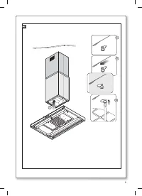
(Fig. M1)
- Lift the hood body so that its lower holes are centred on the 4 M5 metrics screws of the
motor chamber (CM). Shift the motor chamber (CM) sideways so that the metric screws are
positioned on the slots and then tighten them permanently.
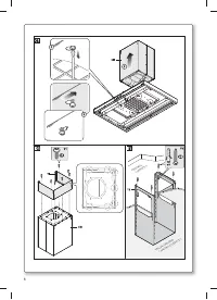
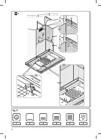
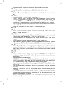
Phase 3
(Fig. N1)
- Remove the paper tape, unscrew the 4 M4 metric screws (V5) previously screwed onto the
extension support elements (SP) and slide the chimney-extension set (G+H) downwards.
- Perform the following connections:
EXHAUST -> NRS pipe + elbow (A+B) to exhaust pipe (F). For the filter version (see sec. F)
the air exhaust must be directed towards the extension slots.
ELECTRIC (only after having disconnected power).
- Fasten the extension (H) once again to the extension support elements (SP) with the 4 M4
metric screws (V5).
- Slide the chimney (G) downwards and fasten it to the hood body with the self-threading
screws (V6).
- Reconnect the male connector (CO) to the matching female connector fastened to the hood
body.
- Following the indications in sec. H1, reassemble the metal filters and the eventual perime-
ter suction panel (AP). In the case of the Lumina NRS Island hood, reassemble the front
panel (PN).
- Power the hood complying with the regulations in force (see sec. D of the booklet).
English
Содержание
- 76 íÖïçàóÖëäàÖ ïÄêÄäíÖêàëíàäà; åéçíÄÜ; éëçéÇçõÖ áÄåÖóÄçàü; èéÑäãûóÖçàÖ ùãÖäíêéùçÖêÉàà
- 78 рис
- 80 îàãúíêõ; àçëíêìäñàà èé àáÇãÖóÖçàû à áÄåÖçÖ; åÖíÄããàóÖëäàÖ îàãúíêõ
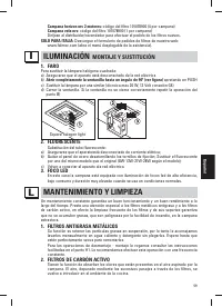
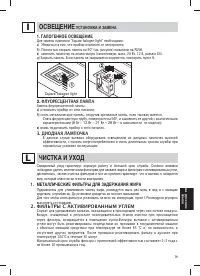
- 81 éëÇÖôÖçàÖ; ìëíÄçéÇäÄ à áÄåÖçÄ; ÉÄãéÉÖççéÖ éëÇÖôÖçàÖ; óàëíäÄ à ìïéÑ; åÖíÄããàóÖëäàÖ îàãúíêõ Ñãü áÄÑÖêÜÄçàü ÜàêÄ
- 82 ÉÄêÄçíàà; Этап
Характеристики

Остались вопросы?Не нашли свой ответ в руководстве или возникли другие проблемы? Задайте свой вопрос в форме ниже с подробным описанием вашей ситуации, чтобы другие люди и специалисты смогли дать на него ответ. Если вы знаете как решить проблему другого человека, пожалуйста, подскажите ему :)


