
Вытяжки Elica OM TOUCH SCREEN WH/F/80 - инструкция пользователя по применению, эксплуатации и установке на русском языке. Мы надеемся, она поможет вам решить возникшие у вас вопросы при эксплуатации техники.
Если остались вопросы, задайте их в комментариях после инструкции.
"Загружаем инструкцию", означает, что нужно подождать пока файл загрузится и можно будет его читать онлайн. Некоторые инструкции очень большие и время их появления зависит от вашей скорости интернета.


9
Use
Model with integrated suction motor
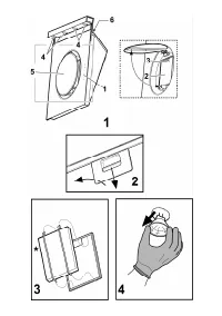
The hood is supplied in the
FILTERING
version and is used
without an extracted fumes discharger conduit.
Fumes and steam are recycled through the
F
deflector.
If you intend using the product in the
SUCTION
version, it is
necessary to have an evacuation conduit going from the upper
B
exit to the extraction hole towards the exterior.
In this case a connection ring has to be installed on the
B
extraction hole and the carbon filter removed.
A telescopic flue is available (as an accessory).
Connect the hood and discharge holes on the walls with a
diameter equivalent to the air outlet (connection flange).
If this is not possible, a multi-connection is supplied for tubes
and discharge holes with a smaller diameter to pressure apply
to the air outlet (connection flange).
The hood will become a little noisier.
Using the tubes and discharge holes on walls with smaller
dimensions will cause a diminution of the suction performance
and a drastic increase in noise.
Any responsibility in the matter is therefore declined.
Attention! If the hood is supplied with carbon filter, then it
must be removed.
Model without integrated suction motor
The models with no suction motor only operate in ducting
mode, and must be connected to an external suction device
(not supplied).
The connecting instructions are supplied with the peripheral
suction unit.
Warning: Only use a peripheral suction unit with total
absorption not higher than 250 W.
Installation
The minimum distance between the supporting surface for the
cooking equipment on the hob and the lowest part of the
range hood must be not less than 30cm from electric cookers
and 35cm from gas or mixed cookers.
If the instructions for installation for the gas hob specify a
greater distance, this must be adhered to.
You will notice a loss in capturing the fumes If the hood is
positioned at a distance greater than that recommended.
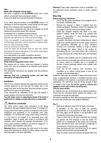
Electrical connection
The mains power supply must correspond to the rating
indicated on the plate situated inside the hood. If provided with
a plug connect the hood to a socket in compliance with current
regulations and positioned in an accessible area, after
installation. If it not fitted with a plug (direct mains connection)
or if the plug is not located in an accessible area, after
installation, apply a double pole switch in accordance with
standards which assures the complete disconnection of the
mains under conditions relating to over-current category III, in
accordance with installation instructions.
Warning!
Before re-connecting the hood circuit to the mains
supply and checking the efficient function, always check that
the mains cable is correctly assembled.
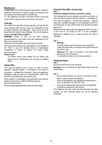
Warning!
Power cable replacement must be undertaken by
the authorised service assistance centre or similar qualified
person.
Mounting
Before beginning installation:
•
Check that the product purchased is of a suitable size for
the chosen installation area.
• Remove the charcoal (*) filter/s if supplied (see also
relative paragraph). This/these is/are to be mounted only
if you want lo use the hood in the filtering version.
• Check (for transport reasons) that there is no other
supplied material inside the hood (e.g. packets with
screws (*), guarantees (*), etc.), eventually removing
them and keeping them.
•
If possible, disconnect and move freestanding or slide-in
range from cabinet opening to provide easier access to
rear wall/ceiling. Otherwise put a thick, protective
covering over countertop, cooktop or range to protect
from damage and debris. Select a flat surface for
assembling the unit. Cover that surface with a protective
covering and place all canopy hood parts and hardware
in it.
•
In addition check whether near the installation area of the
hood (in the area accessible also with the hood mounted)
an electric socket is available and it is possible to
connect a fumes discharge device to the outside (only
suction version).
• Carry out all the masonry work necessary (e.g.
installation of an electric socket and/or a hole for the
passage of the discharge tube).
Expansion wall plugs are provided to secure the hood to most
types of walls/ceilings. However, a qualified technician must
verify suitability of the materials in accordance with the type of
wall/ceiling. The wall/ceiling must be strong enough to take
the weight of the hood.
Do not tile, grout or silicone this
appliance to the wall. Surface mounting only.
Only for some models
An aesthetic flue can be purchased as an optional accessory.
Check with the authorized dealer whether the model in your
possession envisages this possibility.
We advise installing the hood after having purchased the flue
to check with certainty the most suitable installation.
Fig. 5
•
Apply three adhesive strips
C
to the back of the hood.
If necessary (in the case of walls not perfectly
perpendicular or in the presence of walls partly covered
with tiles) apply two
D
spacers in correspondence with
the definitive fixing holes (click fixing).
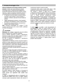
•
Trace a centre line on the wall to facilitate the montage
(1)
, position the hole template so that the middle line
printed on it corresponds to the centre line previously
drawn and that the lower side of the grill corresponds to
the lower part of the hood once mounted
(2)
.
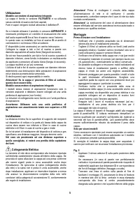
•
Make two holes with the 8 mm Ø drill and fix the support
bracket with two dowels and wall screws
(3)
.
• Open the steam screen and remove the grease filter (see
Характеристики

Остались вопросы?Не нашли свой ответ в руководстве или возникли другие проблемы? Задайте свой вопрос в форме ниже с подробным описанием вашей ситуации, чтобы другие люди и специалисты смогли дать на него ответ. Если вы знаете как решить проблему другого человека, пожалуйста, подскажите ему :)


