
Водонагреватели Timberk SWH FSL2 100 H - инструкция пользователя по применению, эксплуатации и установке на русском языке. Мы надеемся, она поможет вам решить возникшие у вас вопросы при эксплуатации техники.
Если остались вопросы, задайте их в комментариях после инструкции.
"Загружаем инструкцию", означает, что нужно подождать пока файл загрузится и можно будет его читать онлайн. Некоторые инструкции очень большие и время их появления зависит от вашей скорости интернета.


www.timberk.com • electrical storage water heater
www.timberk.com • electrical storage water heater
7
6
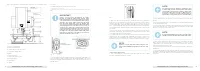
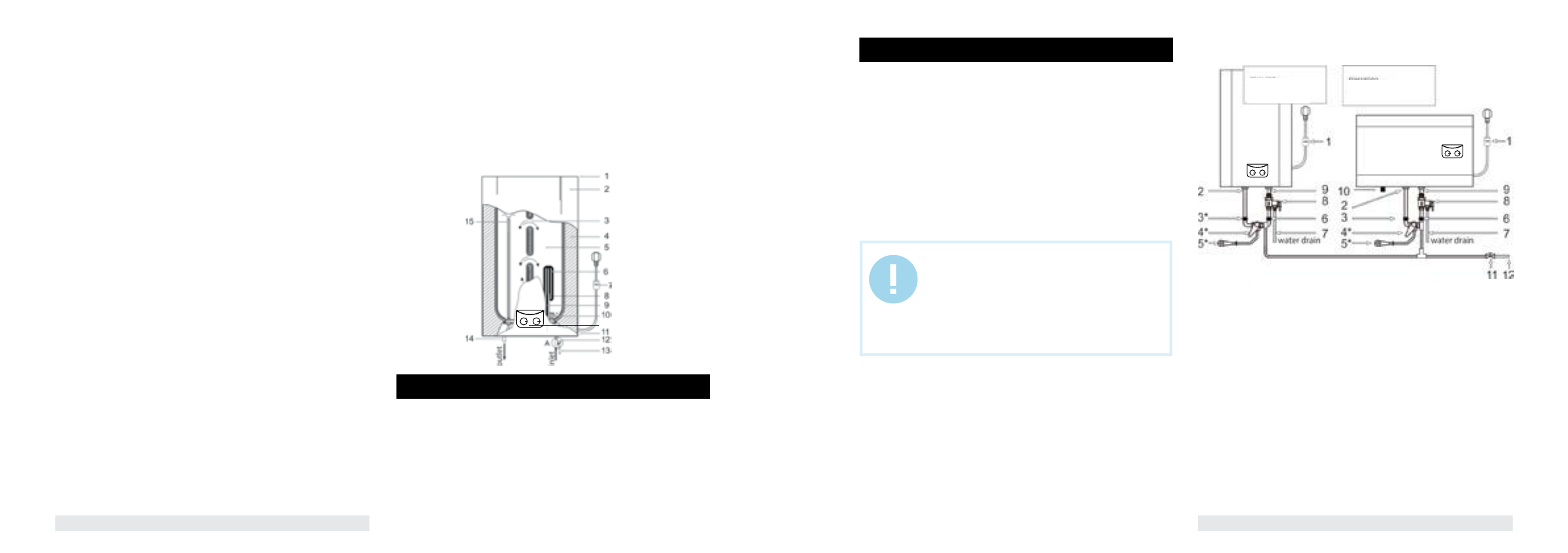
6. DELIVERY SET
7. WATER HEATER INSTALLATION
1. Water heater – 1 pc.
2. Anchor bolt – 2 pcs.
3. Pressure safety valve – 1 pc.
4. Operation manual – 1 pc.
5. Guarantee card – 1 pc.
6. Packing – 1 pc.
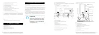
1. Power cord with GFCI**
2. Water outlet
3. Hot water supply adjustment cock*
4. Mixer*
5. Shower header*
6. Cold water supply adjustment cock*
7. Discharge pipe*
8. Composite pressure-relief valve
9. Water inlet
10. Magnesium anode – water discharge nozzle
11. Water main shut-off valve
12. Water main
13. Inlet piple
14. Outlet pipe
* not included in the delivery set
** Depending on the product batch, GFCI can be located not within the power cable electric
plug.
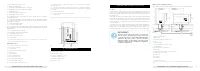
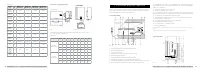
Water heater mounting methods
Fig.5 shows the way to mount the water heater for one consumption point.
Location
1. Electric water heater should be mounted on a firm wall. If the wall is not
robust enough to hold the weight equal to the doubled weight of the total
water heater weight, fully filled with water, then it should be mounted on a
special support.
2. The wall, where the electric water heater is to be mounted, must withstand
at least the double weight of the water heater, fully filled with water; there
must be no cracks and other damages on the wall. Otherwise it is necessary
to take measures to strengthen the mounting or mount the water heater on
a special support.
3. If a bathroom is too small, the water heater can be installed elsewhere,
unexposed to direct sunlight and unavailable for moisture. However, to
reduce heat losses in pipelines, the location, where a water heater is to be
installed, must be as close to the place, where hot water is used, as possible.
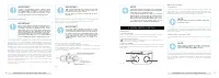
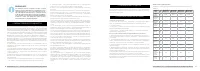
Fig. 4
1 – left composite protective cover
2 – water containing tanks
3 – system of flows between tanks (3 overflows)
4 – the upper part of the hot water intake tube
5 – heating element
6 – right composite protective cover
7 – temperature sensor case**
8 – composite pressure safety valve (be sure to install onto the cold water
supply tube) Pos. A
9 – emergency discharge of surplus water pressure (a small water leakage
is possible from the emergency discharge hole when the water heater is
operating. It is normal)
10 – inlet nozzle with a splitter
11 – hot water outlet nozzle
12 – emergency water discharge valve (can be used for water discharge
during cleaning of the internal tank surface upon its maintenance and anode
replacement)
13 – protective magnesium anode
14 – urethane foam heat insulation layer
15 – external decorative case
16 – power cable with GFCI*
17 - control panel
* Depending on the product batch, GFCI can be located not within the power cable electric plug.
** FSP model eguiped with temperature sensor
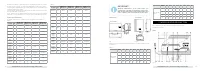
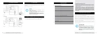
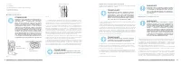
FSL1/FSP1 series
1 – the upper composite protective cover
2 – external decorative case
3 – system of flows
4 – urethane foam heat insulation layer
5 – internal tank
6 – heating element
7 – power cable with GFCI*
8 – thermostat sensor pipe
9 – protective magnesium anode
10 – inlet nozzle with a splitter
11 – the lower composite protective cover
12 – composite pressure safety valve (make sure to install onto the cold water
supply tube) Pos. A
13 – emergency discharge of surplus water pressure (a small water leakage is
possible from the emergency discharge hole when the water heater is operating.
It is normal)
14 – hot water outlet nozzle
15 – the upper part of the hot water intake tube
16 - control panel
* Depending on the product batch, GFCI can be located not within the power cable electric plug.
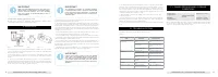
IMPORTANT!
The water heater must be mounted on a vertical wall
only the position, specified in Fig.3-4 (FSL1/FSP1 line
– vertically, FSL2/FSP2 – horizontally). Mounting of the
appliance in any other position or vertical or horizontal
tilting will inevitably result in failure of the water heater,
emergency situation and is considered a non-guarantee
case by the manufacturer.
Fig. 5
FSL1/FSP1
Vertical position
FSL2/FSP2
Horizontal position
16
Содержание
- 2 бора без специального уведомления.
- 9 Уважаемый покупатель!; СОДЕРЖАНИЕ; Серия FSP1; SERIAL NUMBER AND PRODUCTION DATE
- 10 Никогда не используйте водонагреватель, если он неисправен.; МЕРЫ ПРЕДОСТОРОЖНОСТИ; С, при использовании водонагревателя не следует подставлять ча-; РАБОЧИЕ ХАРАКТЕРИСТИКИ; Основные особенности; НАЗНАЧЕНИЕ ПРИБОРА; Технические характеристики; Таблица 1
- 11 Размерные характеристики; ОПИСАНИЕ ВОДОНАГРЕВАТЕЛЯ
- 12 КОМПЛЕКТ ПОСТАВКИ; Местоположение; Способы монтажа водонагревателя
- 13 Магниевый анод- патрубок для слива воды; Подключение к водопроводной магистрали; *не входит в комплект поставки
- 14 УПРАВЛЕНИЕ ВОДОНАГРЕВАТЕЛЕМ; Панель управления; Ручка переключателя режимов мощности; Эксплуатация водонагревателя; Выбор режима мощности
- 15 Температурный дисплей; УСТРАНЕНИЕ НЕИСПРАВНОСТЕЙ; Возможные неисправности и мотоды их устранения
- 16 ЭЛЕКТРИЧЕСКАЯ ПРИНЦИПИАЛЬНАЯ СХЕМА
- 17 • в частично признанной


