Водонагреватели Ariston SB R 50 V-80 V-100 V - инструкция пользователя по применению, эксплуатации и установке на русском языке. Мы надеемся, она поможет вам решить возникшие у вас вопросы при эксплуатации техники.
Если остались вопросы, задайте их в комментариях после инструкции.
"Загружаем инструкцию", означает, что нужно подождать пока файл загрузится и можно будет его читать онлайн. Некоторые инструкции очень большие и время их появления зависит от вашей скорости интернета.
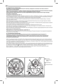

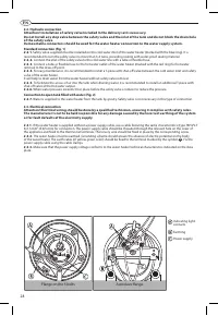
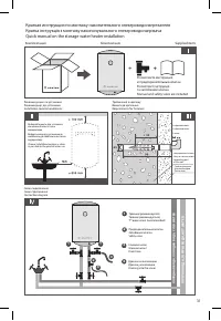
2.2. Hydraulic connection
Note! Installation of safety valve included in the delivery set is necessary.
Do not install any stop valve between the safety valve and the inlet of the tank and do not block the drain hole of the
safety valve.
Demountable connectors should be used for the water heater connection to the water supply system.
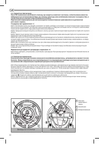
Standard connection (Fig. 1)
2.2.1. Safety valve supplied must be installed on the cold water inlet of the water heater (marked with the blue ring). It is
recommended to turn the safety valve no more than 3−4 turns, providing sealing with water-proof sealing material.
2.2.2.
2.2.3.
2.2.4.
safety valve of the water heater.
It will help to drain water from the water heater without safety valve removal.
2.2.5. To facilitate the access of air into the tank when draining water, it is recommended to install an additional T-piece with
2.2.6. When water pressure exceeds 5 bar, place before the safety valve a reducer to reduce the pressure.
2.2.7. Water is supplied to the water heater from the tank by gravity. For this purpose, the tank water outlet T-piece
supplying water to the heater and other places must be installed higher than the water heater top. Safety valve is not
necessary in this type of connection.
2.3. Electrical connection
manufacturer is not to be held responsible for any damage caused by the incorrect earthing of the system or for fault
defaults of the electricity supply.
2.3.1.
heater.
2.3.2. If the water heater is supplied without a power supply cable, use a cable featuring the same characteristics (type
H05VV-F 3x1,5 mm
2
, Ø 8,5 mm) for connection. The power supply cable should be threaded through the relevant hole on
corresponding screw.
2.3.3.
the symbol
. Fix the power supply cable using the cable clamps.
2.3.4. Make sure that the power supply voltage conforms to the water heater technical characteristics indicated on the data
plate.
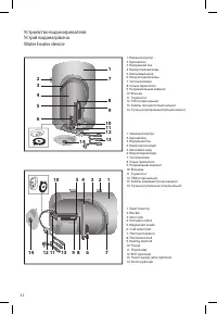
Flange on the 5 bolts
Autoclave flange
Indicating light
contacts
Earthing
Power supply
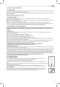
3. STARTING AND OPERATION
3.1. Commissioning
3.1.1.
Before connect the appliance to power source, fill the tank up with mains water. To do this, turn on hot water mixer tap
and then tap of cold water supplied to the water heater.
3.1.2.
Once the water heater is full, the water will flow from the mixer tap. Check the flange for leakages. Center it and tighten
the nuts if necessary.
3.1.3.
Turn the hot water tap on the mixer off.
3.1.4.
Connect the appliance to power source.
3.2. Temperature control
3.2.1.
In models equipped with external control, water temperature can be controlled by a handle connected to the
thermostat in accordance with marks.
3.2.2.
If an appliance model does not have an external control, temperature can be set by turning the adjusting screw of the
thermostat in the range marked by”+” and ”-” signs.
3.2.3.
To do so, disconnect the water heater from the power supply and remove the plastic cover of the appliance.
3.2.4.
It is recommended to install the controller in a position corresponding approximately to 75% of the maximal value. In
this case, the appliance is operated in economy mode significantly reducing the rate of scale formation.
4. MAINTENANCE AND REPAIR WORKS
Attention! Do not try to repair the appliance by yourself. All maintenance and repair works should be carried
out by a qualified technician in conformity with the safety norms and with any provisions set forth in this
manual.
4.1. Water Drain
If there is a possibility that the ambient temperature drops below 0°C in the room where the appliance is installed, drain
water from the water heater.
4.1.1.
Disconnect the appliance from the electrical supply;
4.1.2.
Make sure that the water in the appliance is of safe temperature;
4.1.3.
Turn off the tap of cold water supply to the water heater;
4.1.4.
Turn on the hot water tap on mixer for pressure relief inside the tank;
4.1.5.
Turn on the T-connector stop valve installed at hot water outlet (marked with red ring) for air access into the tank. If it is
absent, remove the connections at the water heater outlet;
4.1.6.
Connect drain hose directed into the sewer to the T-connector stop valve installed at the cold water inlet of the water
heater (marked with the blue ring) and open it. If there is no T-connector, connect the hose to water heater inlet;
4.1.7.
After draining, make sure there is no water inside the water heater.
Freezing of water inside the water heater leads to irreversible changes and defects.
It invalidates all warranty liability on the part of the manufacturer.
4.2. Replacing internal parts
Disconnect the water heater from the electricity supply. Remove the appliance cover. To replace the thermostat pull it straight
out ot the cluster and disconnect from power supply.
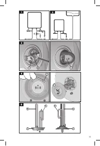
Prior to work, the water heater must first be emptied. For models with an autoclave flange, remove the nut (
D
in Fig. 3), remove
the flange holder (
S
in Fig. 3) and open the flange (
F
in Fig. 3) by pressing it inside. Remove the flange by turning it on its axis.
For models with a flange on the 5 bolts, remove 5 nuts (
C
in Fig. 4) and remove the flange (
F
in Fig. 4). The heating element
and anode rod are attached to the flange. During reassembly, make sure that the heating element, flange gasket and the
thermostat are put back in their original positions. We recommend replacing the flange gasket every time when reassembling.
Prior to any repair or maintenance procedure, disconnect the unit from power source.
Use original spare parts of the manufacturer only.
4.3. Periodical maintenance
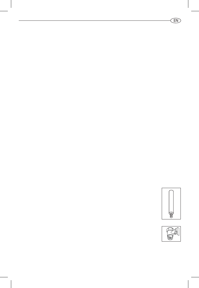
4.3.1. Magnesium anode
The magnesium anode rod is an integral part of the protection system of water tank against corrosion.
It’s necessary to check the condition of the magnesium anode rod ANNUALLY.
In case of severe wear, the magnesium anode rod must be replaced.
The warranty for water tank with the worn magnesium anode rod (residual volume is less than 30%) is not
valid.
The magnesium anode rod should be replaced at least once in 24 months (except for the water heater with the
internal tank made of stainless steel).
The magnesium anode rod is a consumable item that cannot be replaced under warranty.
4.3.2. Safety valve
The safety valve (pressure safety device) must be inspected regularly to check that it is not blocked or
damaged. Replace the valve or remove limescale deposits if necessary. If the safety valve is equipped with a
lever, regular valve correct operation check procedure can be performed with its help.
29
Содержание
- 3 Срок службы изделия
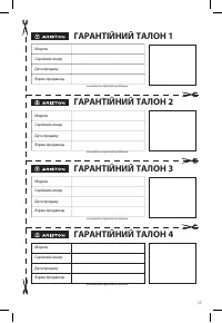
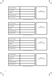
- 6 ГАРАНТИЙНЫЙ ТАЛОН 1
- 8 ОБЩИЕ ТРЕБОВАНИЯ; Монтаж прибора осуществляется за счет пользователя.
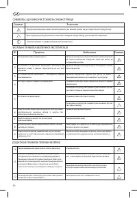
- 10 УСТАНОВКА; ОБЩИЕ ПРАВИЛА БЕЗОПАСНОЙ ЭКСПЛУАТАЦИИ; Символ Значение
- 13 ВКЛЮЧЕНИЕ И РАБОТА
- 14 ГАРАНТІЙНИЙ ТАЛОН; ЕЛЕКТРИЧНІ ВОДОНАГРІВАЧІ; Гарантійний термін на всі водонагрівачі - 1 рік.; Використовується на території України
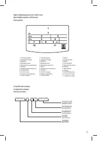
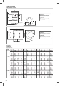
- 32 Устройство водонагревателя; Идентификационная табличка
- 34 Размеры


