
Варочная панель Bertazzoni PM36 1 IG X - инструкция пользователя по применению, эксплуатации и установке на русском языке. Мы надеемся, она поможет вам решить возникшие у вас вопросы при эксплуатации техники.
Если остались вопросы, задайте их в комментариях после инструкции.
"Загружаем инструкцию", означает, что нужно подождать пока файл загрузится и можно будет его читать онлайн. Некоторые инструкции очень большие и время их появления зависит от вашей скорости интернета.

6
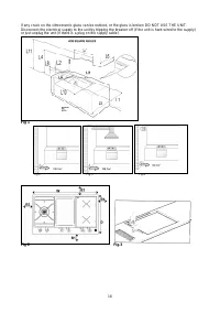
ROOM VENTILATION – LOCATION AND VENTING.
ATTENTION: An exhaust fan may be used with the appliance; in each case it shall be installed in
conformity with the national standards in force.
ATTENTION: Exhaust hood operation may affect other vented appliances; in each case it shall be
installed in conformity with the national standards in force.
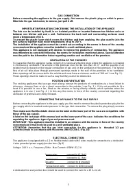
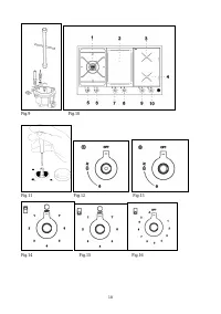
- CHANGING THE NOZZLES FOR USE WITH OTHER TYPES OF GAS:
To change the nozzles of the burners use the following procedure:
Lift up the burners and unscrew the nozzles ( Fig. 9) using an adjustable spanner of 7 mm and change the
nozzles with those designed for the new gas supply according to the information given in TABLE A shown
below.
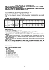
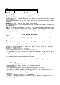
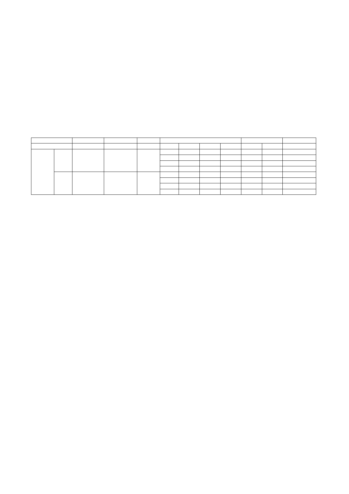
TABLE A: Adapting to different types of gas
Burner Inj.
size
Gas
Pressure
Max Rate
Min Rate
By-pass size
1/100mm
Type
[mbar] g/h l/h kw kcal/h kw
kcal/h 1/100mm
130 Town
G110 8
- 181 0,8 688 0,3 258 27
reg
Inner 70 Natural
G20 20 - 76 0,8 688 0,3 258 27
reg.
46
Butane G30
30
58
-
0,8
688
0,3
258
27
Dual
46 Propane
G31 37 57 - 0,8 688 0,3 258
27
N°2
x
300
Town
G110
8
- 885 4,4 3784 1,8 1548 65
reg
burner
Outer
N°2 x 110
Natural G20
20
-
419
4.4
3784
1,8
1548
65 reg
N°2 x 69
Butane G30
30
298
-
4,1
3526
1,8
1548
65
N°2
x
69
Propane
G31 37 293 -
4,1 3526 1,8 1548
65
CAUTION: save the orifices removed from the appliance for future use
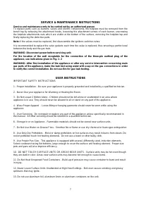
Regulation of burners
Regulation of the "MINIMUM" on the burners
To regulate the minimum on the burners carry out the following procedure indicated below:
1) Turn on the burner and put the knob onto position MINIMUM ( small flame ).
2) Remove the knob ( Fig. 11) of the tap which is set for standard pressure. The knob is found on the bar of
the tap itself.
3) Beside the tap bar on the work top, use a small screwdriver that fits the screw (gold) found on the lower
part of the tap and turn the fixing screw to the right or left until the flame of the burner is regulated in the most
suitable way to MINIMUM.
4) Make sure that that the flame does not go out when changing the position quickly from MAXIMUM to the
MINIMUM position.
ATTENTION: The regulation described above can be carried out only with burners using natural gas,
while with burners using propane gas the screw must be fully screwed in, in a clockwise direction.
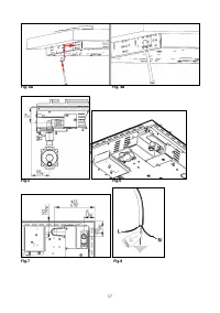
DESCRIPTIONS
DESCRIPTIVE CAPTION FOR HOB (fig.10)
1. Dual burner
2 Electric griddle
3. Rear Induction element
4. Front induction element
5. Dual out burner control knob
6. Dual in burner control knob
7. Rear element griddle control knob
8. Front element griddle control knob
9. Front Induction element control knob
10. Rear Induction element control knob
Характеристики

Остались вопросы?Не нашли свой ответ в руководстве или возникли другие проблемы? Задайте свой вопрос в форме ниже с подробным описанием вашей ситуации, чтобы другие люди и специалисты смогли дать на него ответ. Если вы знаете как решить проблему другого человека, пожалуйста, подскажите ему :)


