
Варочная панель Bertazzoni PM36 1 IG X - инструкция пользователя по применению, эксплуатации и установке на русском языке. Мы надеемся, она поможет вам решить возникшие у вас вопросы при эксплуатации техники.
Если остались вопросы, задайте их в комментариях после инструкции.
"Загружаем инструкцию", означает, что нужно подождать пока файл загрузится и можно будет его читать онлайн. Некоторые инструкции очень большие и время их появления зависит от вашей скорости интернета.


5
GAS CONNECTION
Before connecting the appliance to the gas supply, first remove the plastic plug on which is press-
fitted into the gas inlet union; to remove, just pull it off.
IMPORTANT INFORMATION CONCERNING THE INSTALLATION OF THE APPLIANCE
The hob can be installed by itself, in an isolated position or inserted between two kitchen units or
between one kitchen unit and a wall. Furthermore the back wall and surrounding surfaces must
resist a temperature of 65 K.
To prevent the plastic layer which covers the kitchen unit from ungluing, the glue used to join the
two surfaces together must resist temperatures of up to 150 °C
The installation of the appliance must be carried out according to the norms in force of the country
concerned and the appliance must be installed in a well ventilated place.
This appliance is not equipped with devices to remove the products of combustion. The appliance
must therefore be connected following the norms for installation mentioned above. Special attention
must be paid to the information below regarding aeration and ventilation of the premises.
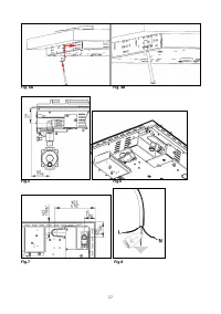
VENTILATION OF THE PREMISES
To guarantee that the appliance works correctly it is necessary that the place where the appliance is installed
is continuously ventilated. The volume of the premises must not be less than 25 m³ and the quantity of air
needed must be based on the regular combustion of gas and on the ventilation of the premises. The natural
flow of air will take place through permanent openings made in the wall of the premises to be ventilated:
these openings will be connected to the outside and must have a minimum section of 100 cm² ( see Fig. 2 ).
These openings must be made in such a way that they cannot be obstructed.
POSITION AND VENTILATION
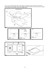
The cooking appliances that use gas must always remove the products of combustion via a hood linked to
chimneys, chimney flues or via a direct connection to the outside ( see Fig. 3 ). If it is not possible to fit a
hood it is possible to use a fan, fitted on the window or facing directly outside, which operates when the
appliance is in use. ( see Fig. 4 ). In this way the norms in force of the country concerned regarding the
ventilation of premises are strictly followed.
CONNECTING THE APPLIANCE TO THE GAS SUPPLY
Before connecting the appliance to the gas supply you first need to remove the plastic protective plug for the
gas supply which is inserted under pressure in the gas inlet connection. To remove the plug simply unscrew
it.
Then make sure that the details shown on the label on the lower part of the case are compatible with
those of the gas supply.
A label on the last page of this manual and on the lower part of the case indicates the conditions for
regulating the appliance: type of gas and pressure used.
IMPORTANT: This appliance must be installed in accordance with the norms in force of the country
concerned and it must only be used in a well-ventilated place.
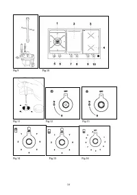
ATTENTION: Remember that the gas inlet connection for the appliance is threaded 1/2 gas
cylindrical male in accordance with the norms UNI-ISO 228-1. (Fig. 10)
ELECTRICAL CONNECTION
The appliance is equipped with a 1.2 m. flexible metal cable with 3 wires ready for connection to a dedicated
4 wire grounded power supply/junction box: (fig.8)
Voltage 240 V a.c., Frequency 50Hz. Max Current: 4500W /22,2 A
brown wire:
connect to L1 (hot)
---------------:
connect to L1 (hot)
blu wire:
connect to N (neutral)
Yellow/Green wire: connect to GND (ground)
A dedicated line and junction box should be used to connect the oven to a 25 A circuit.
Характеристики

Остались вопросы?Не нашли свой ответ в руководстве или возникли другие проблемы? Задайте свой вопрос в форме ниже с подробным описанием вашей ситуации, чтобы другие люди и специалисты смогли дать на него ответ. Если вы знаете как решить проблему другого человека, пожалуйста, подскажите ему :)


