
Варочная панель Bertazzoni CB36 6 00 X - инструкция пользователя по применению, эксплуатации и установке на русском языке. Мы надеемся, она поможет вам решить возникшие у вас вопросы при эксплуатации техники.
Если остались вопросы, задайте их в комментариях после инструкции.
"Загружаем инструкцию", означает, что нужно подождать пока файл загрузится и можно будет его читать онлайн. Некоторые инструкции очень большие и время их появления зависит от вашей скорости интернета.


8
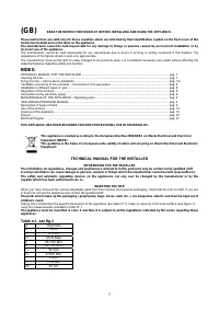
IMPORTANT INFORMATION CONCERNING THE INSTALLATION OF THE APPLIANCE
The hob can be installed by itself, in an isolated position or inserted between two kitchen units or between one kitchen unit
and a wall. Furthermore the back wall and surrounding surfaces must resist a temperature of 65 K.
To prevent the plastic layer which covers the kitchen unit from ungluing, the glue used to join the two surfaces together must
resist temperatures of up to 150 °C
The installation of the appliance must be carried out according to the norms in force of the country concerned and the
appliance must be installed in a well ventilated place.
This appliance is not equipped with devices to remove the products of combustion. The appliance must therefore be
connected following the norms for installation mentioned above. Special attention must be paid to the information below
regarding aeration and ventilation of the premises.
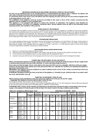
VENTILATION OF THE PREMISES
To guarantee that the appliance works correctly it is necessary that the place where the appliance is installed is continuously ventilated.
The volume of the premises must not be less than 25 m³ and the quantity of air needed must be based on the regular combustion of
gas and on the ventilation of the premises. The natural flow of air will take place through permanent openings made in the wall of the
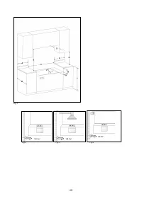
premises to be ventilated: these openings will be connected to the outside and must have a minimum section of 100 cm² ( see Fig. 2 ).
These openings must be made in such a way that they cannot be obstructed.
POSITION AND VENTILATION
The cooking appliances that use gas must always remove the products of combustion via a hood linked to chimneys, chimney flues or
via a direct connection to the outside ( see Fig. 3 ). If it is not possible to fit a hood it is possible to use a fan, fitted on the window or
facing directly outside, which operates when the appliance is in use. ( see Fig. 4 ). In this way the norms in force of the country
concerned regarding the ventilation of premises are strictly followed.
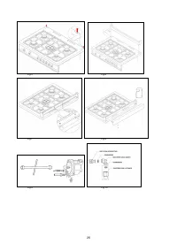
BACKGUARD INSTALLATION INSTRUCTION
1) Remove n°2 screws fixing worktop as shown in fig.5
2) Place front part of the backguard and attach it from bottom side with the two removed screws (point 2) as shown in fig .6
3) Fix the front part of the backguard with the screws supplied with the backguard kit (fig.7)
4) Assemble back part with front part of the backguard and fix them with a screws supplied with the backguard kit (fig.8)
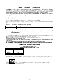
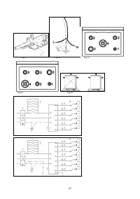
CONNECTING THE APPLIANCE TO THE GAS SUPPLY
Before connecting the appliance to the gas supply you first need to remove the plastic protective plug for the gas supply which
is inserted under pressure in the gas inlet connection. To remove the plug simply unscrew it.
Then make sure that the details shown on the label on the lower part of the case are compatible with those of the gas supply.
A label on the last page of this manual and on the lower part of the case indicates the conditions for regulating the appliance:
type of gas and pressure used.
IMPORTANT: This appliance must be installed in accordance with the norms in force of the country concerned and it must only
be used in a well-ventilated place.
ATTENTION: Remember that the gas inlet connection for the appliance is threaded 1/2 gas cylindrical male in accordance with
the norms UNI-ISO 228-1. (Fig. 10)
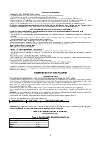
ADAPTING TO DIFFERENT TYPES OF GAS
Before carrying out any maintenance work, disconnect the appliance from the gas and electric supply.
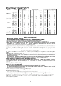
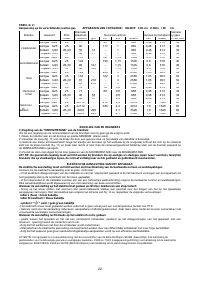
- CHANGING THE NOZZLES FOR USE WITH OTHER TYPES OF GAS:
To change the nozzles of the burners use the following procedure:
Lift up the burners and unscrew the nozzles ( Fig. 9) using an adjustable spanner of 7 mm and change the nozzles with those designed
for the new gas supply according to the information given in TABLE N° 2 shown below.
ATTENTION: After carrying out the changes described above, the technician must put the label corresponding to the new gas
supply on the appliance to take the place of the old label. This label is found in the bag containing spare nozzles.
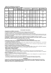
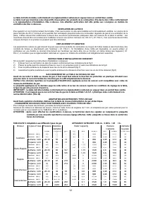
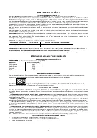
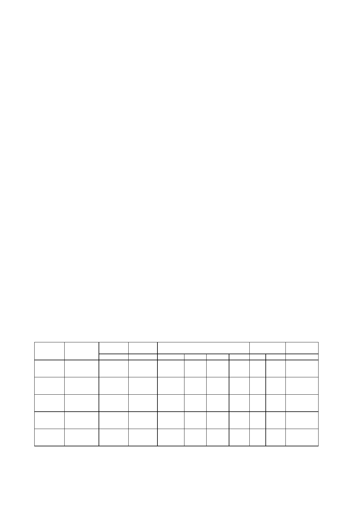
TABLE N°2: Adapting to different types of gas
APPLIANCE CATEGORY: II2H3+
Burner
Types of Gas
Pressure
Nozzle
Diameter
Rater Capacity
Reduced
Capacity
by-pass
Diameter
mbar 1/100
mm. g/h
l/h kw kcal/h
kw
kcal/h
1/100
mm.
Natural G20
20
77
-
95
1
860
0,48
413
34 reg.
Auxiliary
Butane G30
30
50
73
-
1
860
0,48
413
34
Propane
G31
37
50
71
-
1
860
0,48
413
34
Natural G20
20
101
-
167
1,75
1505
0,6
516
36 reg.
Semi-Rapid Butane G30
30
66
127
-
1,75
1505
0,6
516
36
Propane
G31
37
66
125
-
1,75
1505
0,6
516
36
Natural G20
20
129
-
286
3
2580
1,05
903
52 reg.
Rapid
Butane G30
30
87
218
-
3
2580
1,05
903
52
Propane
G31
37
87
214
-
3
2580
1,05
903
52
Dual
Natural G20
20
70
-
76
0,8
688
0,48
413
34 reg.
Inner
Butane G30
30
46
58
-
0,8
688
0,48
413
34
Propane
G31
37
46
57
-
0,8
688
0,48
413
34
Dual
Natural G20
20
2x110
-
419
4,4
3784
1,8
1548
65 reg.
Outer
Butane G30
30
2x69
298
-
4,1
3526
1,8
1548
65
Propane
G31 37 2x69 293 - 4,1
3526
1,8
1548 65
Характеристики

Остались вопросы?Не нашли свой ответ в руководстве или возникли другие проблемы? Задайте свой вопрос в форме ниже с подробным описанием вашей ситуации, чтобы другие люди и специалисты смогли дать на него ответ. Если вы знаете как решить проблему другого человека, пожалуйста, подскажите ему :)


