Триммеры Solo 155 - инструкция пользователя по применению, эксплуатации и установке на русском языке. Мы надеемся, она поможет вам решить возникшие у вас вопросы при эксплуатации техники.
Если остались вопросы, задайте их в комментариях после инструкции.
"Загружаем инструкцию", означает, что нужно подождать пока файл загрузится и можно будет его читать онлайн. Некоторые инструкции очень большие и время их появления зависит от вашей скорости интернета.


17
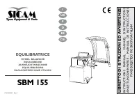
COD. 655632 Rev.0
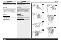
ENGLISH
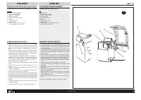
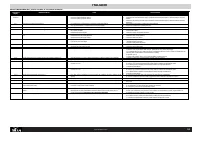
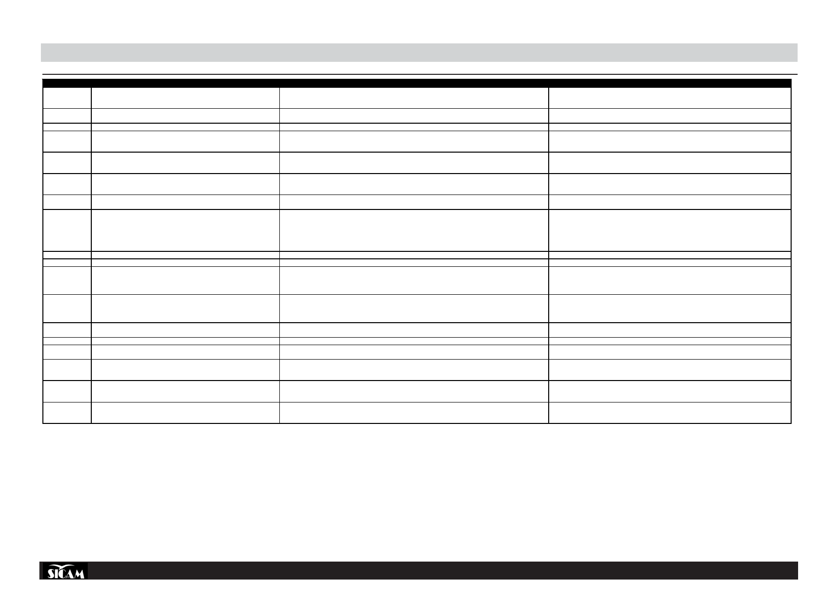
TROUBLESHOOTING
display
malfunctioning
Causes
Trouble-shooting
Displays do not
come on
The card is not powered up.
1.
External supply off or phase not working.
2.
Fuse blown in the electrical plant.
3.
Control panel fuse blown.
1.
Check that positive/negative and neutral are connected up to balancer.
2.
Replace fuses in electrical plant (blown fuses indicate fault in electric plant)
3.
Replace fuses on control panel (blown fuses indicate fault in electronic part).
Err 1
Err 1 appears on power-up
1.
The card has lost the calibration data and factory configuration setting.
2.
One or more calibration or setting phases have not been carried out.
1.
Repeat all calibration and balancer configuration stages
2.
Perform missing programming or setting operations.
Err 2
During the measuring cycle the Err 2 message appears.
1.
The guard has been raised before completion of measurements.
1.
Wait for end of measuring launch before raising guard.
Err 3
During the measuring cycle the Err 3 message appears.
1.
On start-up (using START key or lowering guard) the wheel was rotating backwards
2.
Motor winding inverted.
1.
Ascertain that the wheel is still before start-up and in any case avoid rotating wheel backwards on
START.
2.
Check for correct motor connection.
Err 4
The motor does not turn (with START pressed) or after about 20 sec. the Err 4
message appears.
1.
The motor cannot reach the revolutions needed for effective balancing
2. electronic
card
malfunctioning
3. electrical
plant
malfunctioning
1.
Check mains voltage (it is probably low)
2.
Replace electronic card
3.
Replace electrical part
Err 5
At end of second calibrating run with the wheel Err 5 appears on the display.
1.
Calibration weight has not been applied on the wheel.
2.
The pick-ups have not been connected
1.
Repeat calibration from beginning and apply the calibration weight when instructed in the calibration
procedure (also see “Basic Machine Calibration”)
2. Check
pick-up
connections.
Err 6
Message Err 6 appears when pressing the START key.
1.
The guard has not been lowered.
2.
Guard microswitch broken
1.
Lower guard with wheel mounted.
2. Replace
microswitch.
Err 7
At end of second calibrating run with the wheel Err 7 appears on the display
1.
Phase difference between the 2 pick-ups is too large.
1.
a) check that the calibration weight has been correctly applied;
b) also check machine location; it is probably not stable and is vibrating excessively;
c) if the problem persists after having stabilised the machine correctly, check the sensor and
electronic card connections (and replace if necessary);
d) replace pick-ups;
e) if after replacing pick-ups the problem is not solved, replace the card.
Err 8
At end of second calibrating run with the wheel Err 8 appears on the display
1.
The left pick-up has not been correctly connected or is defective or the cable is disconnected.
1.
Check left pick-up connection (and replace if necessary).
Err 9
At end of second calibrating run with the wheel Err 9 appears on the display
1.
The right pick-up has not been correctly connected or is defective or the cable is disconnected.
1.
Check right pick-up connection (and replace if necessary).
Err 10
During launch Err 10 appears on the display.
1.
Position sensors in optoelectronics defective.
2.
The motor will not turn
1.
a) check optoelectronic card connection.
b) check the optoelectronic card is protected from daylight and cover if necessary;
c) if the defect persists check and if necessary replace the optoelectronic card.
2.
Check electrical part.
Err 11
During launch Err 11 appears on the display.
1.
Passage through zero sensor defective in optoelectronics
2.
The motor will not turn
1.
a) check optoelectronic card connection.
b) check the optoelectronic card is protected from daylight and cover if necessary;
c) if the defect persists check and if necessary replace the optoelectronic card.
2.
Check electrical part.
Err 17
At end of launch Err 17 appears on display
1.
Weight out of regulation field (weight necessary for balancing the wheel is above 500 grams)
1.
a) Check that the wheel is correctly fixed on the flange;
b) find (in any case) the external position, apply a 100 gram weight and launch a run..
Err 18
Err 18 appears on display
1.
Wheel data not set.
1.
Set the wheel data before starting the measuring cycle.
Err 19
“Err 19” is displayed after the second calibration cycle.
1.
The signal reading at the right pick-up is lower than that at the left pick-up.
1.
The connections to the two pick-ups might be inverted. Check (and exchange if necessary).
Err 20
During measuring cycle Err 20 appears on display: the wheel speed has gone
below the minimum for measurability.
1.
1 Brake pedal operated during the measurement
2.
Motor rotation speed irregular.
1.
Avoid pressing the brake pedal when the motor is operating.
2.
beware of knocking the machine during the measuring cycle. check mains voltage (probably low)
Err 21
During measuring cycle Err 21 appears on display: possible electrical fault.
1.
The electronic card has found a condition of danger connected to a too-high wheel speed during an inactive
machine phase (the shaft rotates at high speed without the operator having pressed the START command); the
electric power is deactivated.
1.
Switch off the machine, lower the guard and switch the machine back on without moving the wheel; if
the error persists, check (and replace if necessary) the electric or electronic part (control panel or
encoder card).
Err 22
During the launch Err 22 appears on display
1.
Some fault in the optoelectronic signals.
1.
a) check the optoelectronic card is protected from daylight and cover if necessary;
b) if the defect persists check and if necessary replace the optoelectronic card.
c) check and if necessary replace the control panel electronic card.
Характеристики

Остались вопросы?Не нашли свой ответ в руководстве или возникли другие проблемы? Задайте свой вопрос в форме ниже с подробным описанием вашей ситуации, чтобы другие люди и специалисты смогли дать на него ответ. Если вы знаете как решить проблему другого человека, пожалуйста, подскажите ему :)
