
Шуруповерты Makita HP002GZ - инструкция пользователя по применению, эксплуатации и установке на русском языке. Мы надеемся, она поможет вам решить возникшие у вас вопросы при эксплуатации техники.
Если остались вопросы, задайте их в комментариях после инструкции.
"Загружаем инструкцию", означает, что нужно подождать пока файл загрузится и можно будет его читать онлайн. Некоторые инструкции очень большие и время их появления зависит от вашей скорости интернета.

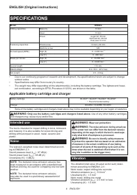


8 ENGLISH
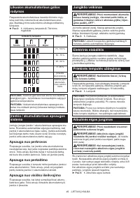
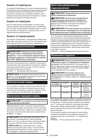
Speed change
CAUTION:
Always set the speed change lever
fully to the correct position.
If you operate the
tool with the speed change lever positioned halfway
between the "1" side and "2" side, the tool may be
damaged.
CAUTION:
Do not use the speed change lever
while the tool is running.
The tool may be damaged.
Displayed
Number
Speed
Torque
Applicable
operation
1
Low
High
Heavy load-
ing operation
2
High
Low
Light loading
operation
To change the speed, switch off the tool first. Push the speed
change lever to display "2" for high speed or "1" for low speed
but high torque. Be sure that the speed change lever is set to
the correct position before operation.
If the tool speed is coming down extremely during the
operation with display "2", push the lever to display "1"
and restart the operation.
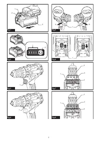
►
Fig.6:
1.
Speed change lever
Selecting the action mode
CAUTION:
Always set the ring correctly to
your desired mode mark. If you operate the tool
with the ring positioned halfway between the
mode marks, the tool may be damaged.
CAUTION:
When you change the position
from "
" to other modes, it may be a little dif-
ficulty to slide the action mode changing ring. In
this case, switch on and run the tool for a second
at the "
" position, then stop the tool and slide
the ring to your desired position.
This tool has three action modes.
•
Drilling mode (rotation only)
•
Hammer drilling mode (rotation with
hammering)
•
Screwdriving mode (rotation with clutch)
Select one mode suitable for your work. Turn the
action mode changing ring and align the mark that you
selected with the arrow on the tool body.
►
Fig.7:
1.
Action mode changing ring
2.
Adjusting
ring
3.
Mark
4.
Arrow
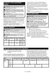
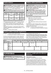
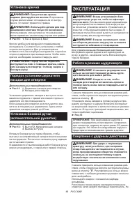
Adjusting the fastening torque
►
Fig.8:
1.
Action mode changing ring
2.
Adjusting
ring
3.
Graduation
4.
Arrow
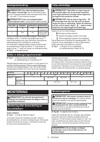
The fastening torque can be adjusted in 21 levels by
turning the adjusting ring. Align the graduations with
the arrow on the tool body. You can get the minimum
fastening torque at 1 and maximum torque at 21.
Before actual operation, drive a trial screw into your
material or a piece of duplicate material to determine
which torque level is required for a particular applica-
tion. The following shows the rough guide of the rela-
tionship between the screw size and graduation.
Graduation
1
2
3
4
5
6
7
8
9
10 11 12 13 14 15 16 17 18 19 20 21
Machine screw
M4
M5
M6
Wood
screw
Soft wood
(e.g. pine)
–
ø
3.5 x 22
ø4.1x 38
–
Hard wood
(e.g. lauan)
–
ø
3.5 x 22
ø4.1x 38
–
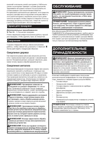
ASSEMBLY
CAUTION:
Always be sure that the tool is
switched off and the battery cartridge is removed
before carrying out any work on the tool.
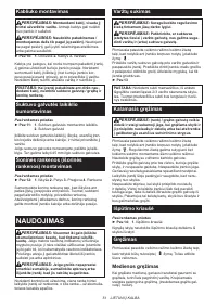
Installing or removing driver bit/
drill bit
Optional accessory
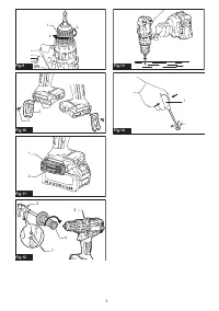
►
Fig.9:
1.
Sleeve
2.
Close
3.
Open
Turn the sleeve counterclockwise to open the chuck
jaws. Place the driver bit/drill bit in the chuck as far
as it will go. Turn the sleeve clockwise to tighten the
chuck. To remove the driver bit/drill bit, turn the sleeve
counterclockwise.
Installing hook
CAUTION:
When installing the hook, always
secure it with the screw firmly.
If not, the hook
may come off from the tool and result in the personal
injury.
CAUTION:
Use the hanging/mounting parts
for their intended purposes only.
Using for unin-
tended purpose may cause accident or personal
injury.
►
Fig.10:
1.
Groove
2.
Hook
3.
Screw
The hook is convenient for temporarily hanging the tool.
This can be installed on either side of the tool. To install
the hook, insert it into a groove in the tool housing on
either side and then secure it with a screw. To remove,
loosen the screw and then take it out.
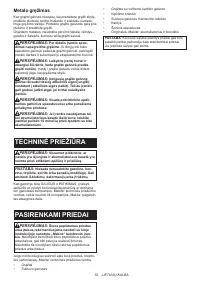
NOTICE:
When hanging the tool on your belt
using the hook, remove the driver bit/drill bit and
the side grip.
Содержание
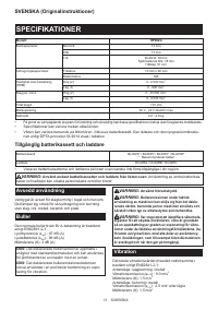
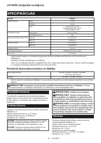
- 60 ТЕХНИЧЕСКИЕ ХАРАКТЕРИСТИКИ; Подходящий блок аккумулятора и зарядное устройство
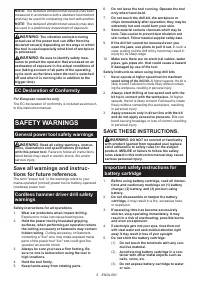
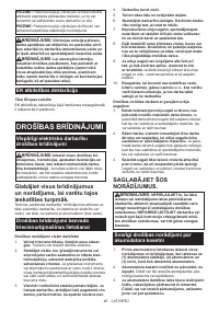
- 61 МЕРЫ БЕЗОПАСНОСТИ; Сохраните брошюру с инструк
- 62 Важные правила техники; СОХРАНИТЕ ДАННЫЕ
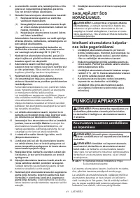
- 63 Советы по обеспечению мак; ОПИСАНИЕ РАБОТЫ
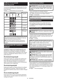
- 64 Защита от перегрузки
- 65 Выбор режима действия; СБОРКА; Установка или снятие насадки для
- 66 ЭКСПЛУАТАЦИЯ
- 67 Груша для продувки; Сверление; ОБСЛУЖИВАНИЕ
Характеристики

Остались вопросы?Не нашли свой ответ в руководстве или возникли другие проблемы? Задайте свой вопрос в форме ниже с подробным описанием вашей ситуации, чтобы другие люди и специалисты смогли дать на него ответ. Если вы знаете как решить проблему другого человека, пожалуйста, подскажите ему :)


