
Шуруповерты GRAPHITE Energy+ 58G019 - инструкция пользователя по применению, эксплуатации и установке на русском языке. Мы надеемся, она поможет вам решить возникшие у вас вопросы при эксплуатации техники.
Если остались вопросы, задайте их в комментариях после инструкции.
"Загружаем инструкцию", означает, что нужно подождать пока файл загрузится и можно будет его читать онлайн. Некоторые инструкции очень большие и время их появления зависит от вашей скорости интернета.


14
par tially discharged. When only one diode is lit, the batter y is
discharged and must be recharged.
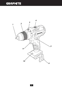
S P I N D L E B R A K E
Drill is equipped with electronic brake that stops the spindle
immediately after the switch button (
9
) is released. The brake
ensures precision when screwing or drilling and prevents free
spindle rotation after switching off.
OPERATION / SET TINGS
S W I TC H I N G O N / S W I TC H I N G O F F
Switching on
– press the switch button (
9
).
Switching off
– release the switch button (
9
).
Each time the switch button (
9
) is pressed, the LED diode (
10
)
lights up to illuminate the workplace.
ROTATIONAL SPEED CONTROL
Increase or reduce pressure on the switch button (
9
) to adjust
drilling or driving speed while operating. Speed adjustment
allows for a soft star t, which prevents dill slipping when drilling
holes in gypsum or glaze, and allows for operation control when
driving screws in and out.
OV E R LOA D C LU TC H
Set the torque adjustment ring (
3
) in appropriate position
to permanently set overload clutch to defined torque value.
When the set torque is reached, overload clutch disconnects
automatically. It prevents from driving screws too deep or
damaging the drill.
TO RQUE ADJUSTMENT
•
Different screws and materials require different torque to be
applied.
•
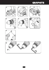
The bigger the number corresponding to given position, the
bigger is the torque (
fig. D
).
•
Set the torque adjustment ring (
3
) to appropriate torque value.
•
Always star t operation with low torque.
•
Increase the torque gradually until obtaining desired results.
•
Use higher settings to undo screws.
•
When drilling, choose setting marked with the drill symbol.
The torque is the greatest with this setting.
•
Knowledge how to choose appropriate torque setting comes
with practice.
Setting the torque adjustment ring in the drilling position
deactivates the overload clutch.
WO R K I N G TO O L I N S TA L L AT I O N
•
Set the direction selector switch (
5
) in the middle position.
•
By turning the ring of the quick release chuck (
2
) counter
clockwise (see mark on the ring) you can spread jaws enough
to inser t drill or driver bit (
fig. E
).
•
To fix the working tool, turn the ring of the quick release chuck
(
2
) clockwise and tighten.
Deinstallation of the tool is similar to installation, only the
sequence of actions is reversed.
Make sure the tool position is correct when installing drill or
driver bit in the quick release chuck. Use additional magnetic
adapter as an extension when using shor t driver bits.
RIGHT-LEFT DIREC TION OF ROTATION
Choose direction of spindle rotation with the direction selector
switch (
5
) (
fig. F
).
Clockwise rotation
– set the switch (
5
) to the extreme left
position.
Counter-clockwise rotation
– set the switch (
5
) to the extreme
right position.
* In cer tain cases position of the switch related to rotation may be different
than specified. Please refer to graphic signs located on the switch or tool
body.
Safe position of the direction selector switch (
5
) is in the middle,
it prevents accidental star ting of the power tool.
•
Drill cannot be star ted, when the switch is in this position.
•
Use this position of the switch to change drills or bits.
•
Before star ting the tool make sure the position of the direction
selector switch (
5
) is correct.
Do not change direction of rotation when the drill spindle
is rotating.
C H A N G E O F G E A R
Gear switch (
4
) (
fig. H
) allows to increase the range of rotational
speed.
Gear I:
small speed range, big torque
Gear II:
greater speed range, small torque.
Set the gear switch in position appropriate for the works to
per form. When the switch is blocked and cannot be moved, turn
the spindle slightly.
Never change the gear switch position when the drill is
operating. It may damage the power tool.
Long lasting drilling at low rotational speed of the spindle
may cause motor overheating. Long lasting drilling at
low rotational speed of the spindle may cause motor
overheating.
H O L D E R
The drill provides convenient holder (
6
) that allows to e.g. hang
the tool on a tool belt when working at heights.
OPERATION AND MAINTENANCE
Remove the battery from the device before commencing
any activities related to installation, adjustment, repair or
maintenance.
M A I N T E N A N C E A N D S TO R AG E
•
Cleaning the device after each use is recommended.
•
Do not use water or any other liquid for cleaning.
•
Clean the tool with a dr y cloth or blow through with
compressed air at low pressure.
•
Do not use any cleaning agents or solvents, they may damage
plastic par ts.
•
Clean ventilation holes in the motor casing regularly to
prevent device overheating.
•
Always store the tool in a dr y place, beyond reach of children.
•
Store the device with the batter y removed.
Q U I C K R E L E A S E C H U C K R E P L AC E M E N T
Quick-release chuck is screwed onto spindle of the drill and
additionally secured with a screw.
•
Set the direction selector switch (
5
) in the middle position.
•
Open jaws of quick release chuck (
1
) and unscrew the fixing
screw (left-hand thread) (
fig. H
).
•
Install hexagonal key in the quick release chuck and tap the
other end of the key.
•
Unscrew the quick release chuck.
•
Installation of the quick release chuck is similar to
deinstallation, only the sequence of actions is reversed.
All defects should be repaired by ser vice workshop authorized
by the manufacturer.


