
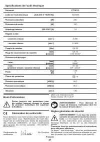
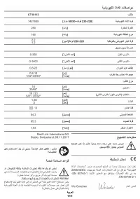
Шуруповерты CROWN CT10113 - инструкция пользователя по применению, эксплуатации и установке на русском языке. Мы надеемся, она поможет вам решить возникшие у вас вопросы при эксплуатации техники.
Если остались вопросы, задайте их в комментариях после инструкции.
"Загружаем инструкцию", означает, что нужно подождать пока файл загрузится и можно будет его читать онлайн. Некоторые инструкции очень большие и время их появления зависит от вашей скорости интернета.


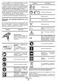


19
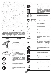
English
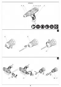
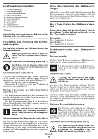
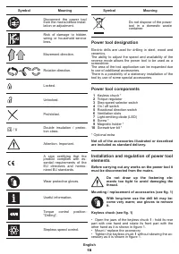
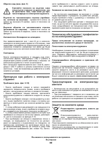
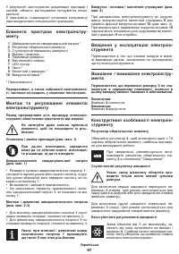
Mounting / dismounting of the keyless chuck (see
fig. 2-3)
•
To mount the keyless chuck
1
, carry out the op-
erations in consecutive stages as it is shown in
figure 2.
•
To dismount the keyless chuck
1
, carry out the oper-
ations in consecutive stages as it is shown in figure 3.
Attention: keep in mind that in the pro-
cess of mounting / dismounting of the
drill chuck the screw 8 has a left-hand
thread.
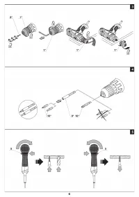
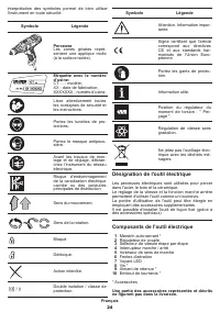
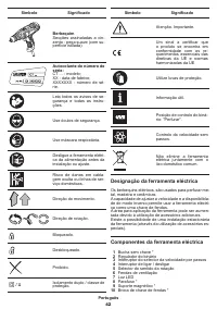
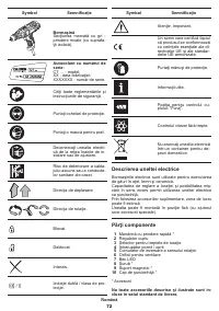
Screwdriver bit / magnetic holder (see fig. 4)
When using the power tool as a screwdriver, use
magnetic holder
9
for reliable locking of screwdriver
bits
10
(see fig. 4). A magnetic holder
9
is not needed
for extended screwdriver bits
10
(specially purposed
for screwdrivers)�
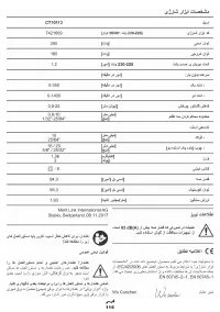
Initial operating of the power tool
Always use the correct supply voltage: the power sup-
ply voltage must match the information quoted on the
power tool identification plate.
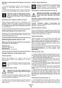
Switching the power tool on / off
Make sure that the reverse switch 5 is not centred;
this blocks on / off switch 4.
Switching on:
Press on / off switch
4
�
Switching off:
Release the on / off switch
4
�
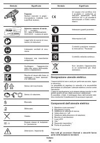
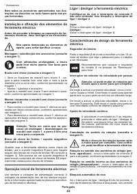
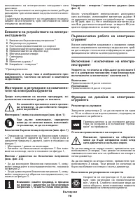
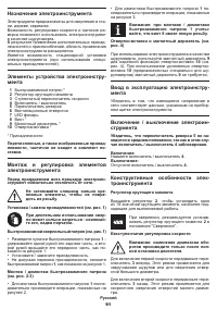
Design features of the power tool
Torque regulator
Rotate the regulator
2
in order to set one of
the 18 torque values most suitable for the work
performed�
It is recommended to set the torque regula-
tor
2
into the position "Drill" to perform drill-
ing�
Step speed selector switch
Attention: one can only change the revo-
lutions per minute range after the engine
fully stops.
In order to put in the first gear, move the switch
3
for-
ward� This mode is used for the fastening of screws or
for large diameter hole drilling�
In order to put in the second gear, move the switch
3
back� This mode is used for speed drilling of small di-
ameter holes�
Stepless speed adjustment
Speed is controlled from 0 to maximum by
pressing force of on / off switch
4
� Weak
pressing results in low revolutions, which
enable a smooth power tool switch-on�
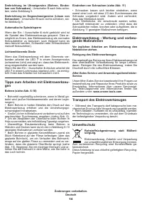
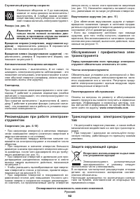
Changing the rotational directions (see fig. 5)
Change the direction of rotation only
after a full stop of the motor, acting oth-
erwise may cause damage to the power
tool.
Clockwise rotation (drilling, fastening of screws)
-
move the rotational direction switch
5
to the left as it is
shown in fig. 5.
Counter clockwise rotation (unscrewing the
screws)
- move the rotational direction switch
5
to the
right as it is shown in fig. 5.
Spindle automatic locking
If the on / off switch
4
is not pressed, the spindle of the
power tool is locked this enables to use the power tool
as an ordinary screwdriver (for example it can be used
to tighten manually screws or bolts)�
Light-emitting diode
When the power tool is connected to the mains, the
LED
7
operates in an indicator mode (low light) and
shows that the power tool is ready to be turned on�
When you press the on / off switch
4
, the LED
7
oper-
ates in a mode of light (strong light) it allows you to
work in low light conditions�
Recommendations on the power tool
operation
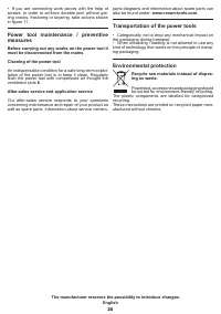
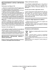
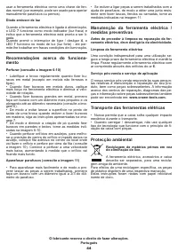
Drilling (see fig. 6-10)
•
Grease the drill bit regularly when drilling holes in met-
als (except drilling non-ferrous metals and their alloys)�
•
When drilling hard metals, apply more force to the
power tool and lower the rotation speed�
•
When drilling large diameter holes in metal, first drill
a hole with a smaller diameter and ream it till the nec-
essary diameter (see. fig. 6).
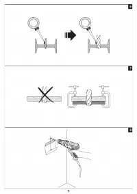
•
In order to avoid splitting of the surface at an exit
point of a drill bit when drilling holes in wood, follow the
instructions shown in figure 7.
•
In order to decrease dust production when drilling
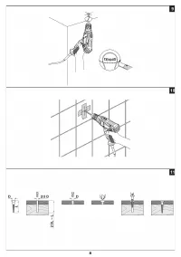
holes in walls and ceilings, take actions indicated in
fig. 8-9.
•
When drilling holes in glazed ceramic tiles, in order
to improve the drill centering accuracy and to save
the glaze from damage, apply adhesive tape to the
presumed hole center and drill after that (see fig. 10).
Start drilling at lower speed increasing it as the hole
deepens�
Screwing the screws (see fig. 11)
•
To make fastening of screws easier and in order to
prevent cracking of the work pieces, first drill a hole
with a diameter equal to 2/3 of a diameter of the screw�


