
Шлифмашины Makita DGA519Z - инструкция пользователя по применению, эксплуатации и установке на русском языке. Мы надеемся, она поможет вам решить возникшие у вас вопросы при эксплуатации техники.
Если остались вопросы, задайте их в комментариях после инструкции.
"Загружаем инструкцию", означает, что нужно подождать пока файл загрузится и можно будет его читать онлайн. Некоторые инструкции очень большие и время их появления зависит от вашей скорости интернета.


14 ENGLISH
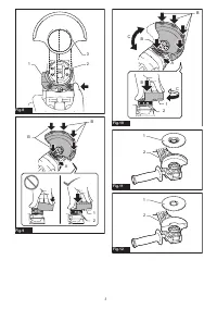
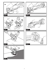
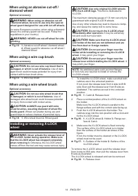
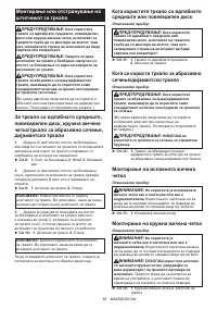
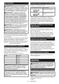
When using an abrasive cut-off /
diamond wheel
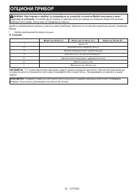
Optional accessory
WARNING:
When using an abrasive cut-off
/ diamond wheel, be sure to use only the special
wheel guard designed for use with cut-off wheels.
(In some European countries, when using a diamond
wheel, the ordinary guard can be used. Follow the
regulations in your country.)
WARNING:
NEVER use cut-off wheel for side
grinding.
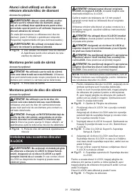
►
Fig.12:
1.
Abrasive cut-off wheel / diamond wheel
2.
Wheel guard for abrasive cut-off wheel /
diamond wheel
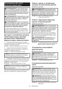
When using a wire cup brush
Optional accessory
CAUTION:
Do not use wire cup brush that is
damaged, or which is out of balance.
Use of dam-
aged brush could increase potential for injury from
contact with broken brush wires.
►
Fig.13:
1.
Wire cup brush
When using a wire wheel brush
Optional accessory
CAUTION:
Do not use wire wheel brush that
is damaged, or which is out of balance.
Use of
damaged wire wheel brush could increase potential
for injury from contact with broken wires.
CAUTION:
ALWAYS use guard with wire
wheel brushes, assuring diameter of wheel fits
inside guard.
Wheel can shatter during use and
guard helps to reduce chances of personal injury.
►
Fig.14:
1.
Wire wheel brush
2.
Wheel guard
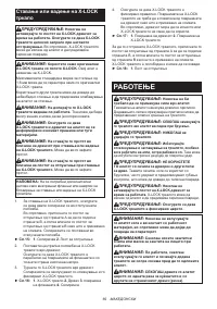
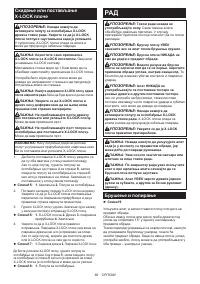
Installing or removing X-LOCK
wheel
WARNING:
Never actuate the release lever of
the X-LOCK holder during operation. Make sure
that the X-LOCK wheel has stopped completely
when removing it.
Otherwise, the X-LOCK wheel
comes off from the tool and may cause serious injury.
CAUTION:
Use only original X-LOCK wheels
with the X-LOCK logo.
This tool is dedicated to
X-LOCK.
The maximum clamping gauge of 1.6 mm can only be
guaranteed with original X-LOCK wheels.
Use of any other wheels may lead to insecure clamp
-
ing, and cause the clamp tool to come loose.
CAUTION:
Do not touch the X-LOCK wheel
immediately after operation.
It may be extremely
hot and could burn your skin.
CAUTION:
Make sure that the X-LOCK wheel
and holder of the tool are not deformed and are
free from dust or foreign matters.
CAUTION:
Do not put your finger near the
holder while installing or removing the X-LOCK
wheel.
It may pinch your finger.
CAUTION:
Do not put your finger near the
release lever while installing the X-LOCK wheel.
It
may pinch your finger.
NOTE:
No additional parts such as inner flanges
or lock nuts are required to install or remove the
X-LOCK wheels.
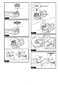
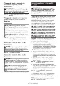
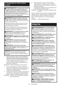
1. To install the X-LOCK wheel, make sure that both
catches are in the unlocked position.
If not, push the release lever from A side to lift B
side, then pull the release lever from B side as
illustrated. The catches are set in the unlocked
position.
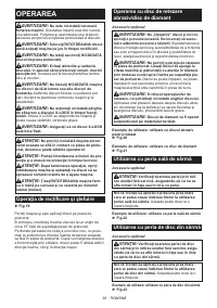
►
Fig.15:
1.
Catch
2.
Release lever
2. Place a central position of the X-LOCK wheel on
the holder.
Make sure the X-LOCK wheel is parallel to the
flange surface and with the correct side facing up.
3. Push the X-LOCK wheel into the holder. The
catches snap into the lock position with a click and
fix the X-LOCK wheel.
►
Fig.16:
1.
X-LOCK wheel
2.
Holder
3.
Flange sur
-
face
4.
Catch
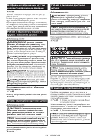
4. Make sure the X-LOCK wheel is fixed correctly.
The surface of the X-LOCK wheel is no higher
than the surface of the holder as shown in the
figure.
If not, the holder must be cleaned or the X-LOCK
wheel must not be used.
►
Fig.17:
1.
Surface of the holder
2.
Surface of the
X-LOCK wheel
To remove the X-LOCK wheel, push the release lever
from A side to lift B side, then pull the release lever from
B side as illustrated.
The X-LOCK wheel is released and can be removed.
►
Fig.18:
1.
Release lever
Содержание
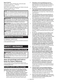
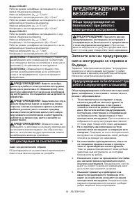
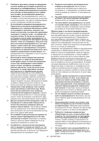
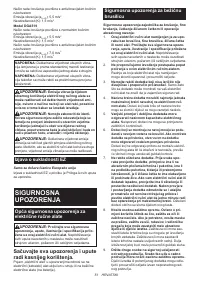
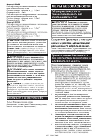
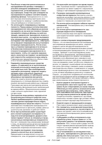
- 107 МЕРЫ БЕЗОПАСНОСТИ; Сохраните брошюру с инструк
- 110 СОХРАНИТЕ ДАННЫЕ; Важные правила техники
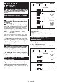
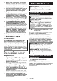
- 111 ОПИСАНИЕ РАБОТЫ; Установка или снятие блока
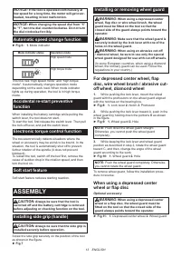
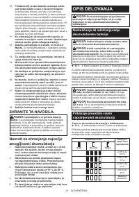
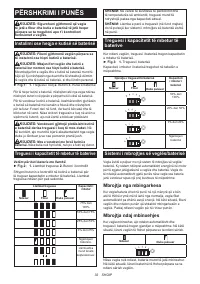
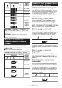
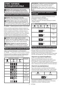
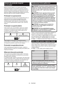
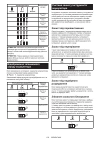
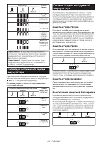
- 112 Индикация оставшегося заряда
- 113 СБОРКА
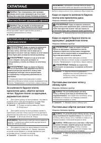
- 114 Установка или снятие кожуха; Установка или снятие диска
- 115 ЭКСПЛУАТАЦИЯ; Шлифовка и зачистка
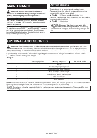
- 116 ОБСЛУЖИВАНИЕ
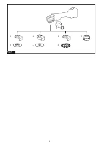
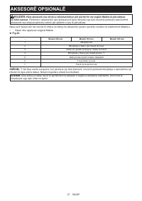
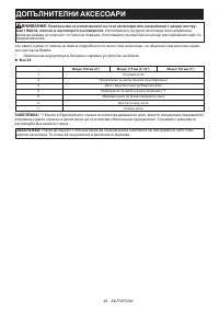
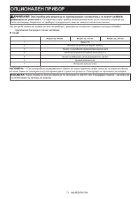
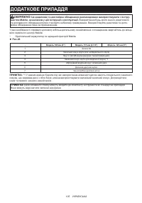
- 117 ДОПОЛНИТЕЛЬНЫЕ ПРИНАДЛЕЖНОСТИ
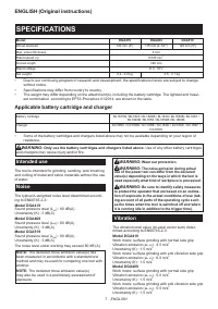
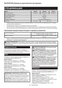
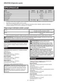
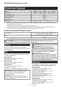
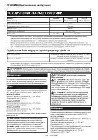
Характеристики

Остались вопросы?Не нашли свой ответ в руководстве или возникли другие проблемы? Задайте свой вопрос в форме ниже с подробным описанием вашей ситуации, чтобы другие люди и специалисты смогли дать на него ответ. Если вы знаете как решить проблему другого человека, пожалуйста, подскажите ему :)


