Пилы дисковые Bosch GKS 85 G (060157A900) - инструкция пользователя по применению, эксплуатации и установке на русском языке. Мы надеемся, она поможет вам решить возникшие у вас вопросы при эксплуатации техники.
Если остались вопросы, задайте их в комментариях после инструкции.
"Загружаем инструкцию", означает, что нужно подождать пока файл загрузится и можно будет его читать онлайн. Некоторые инструкции очень большие и время их появления зависит от вашей скорости интернета.

English |
17
Bosch Power Tools
1 609 92A 2AZ | (30.3.16)
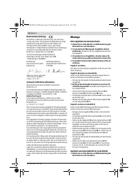
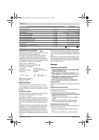
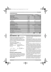
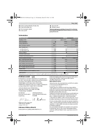
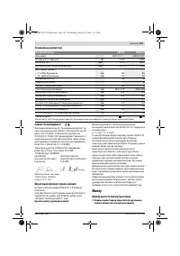
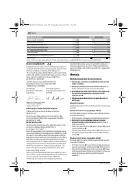
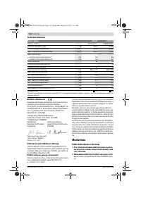
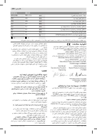
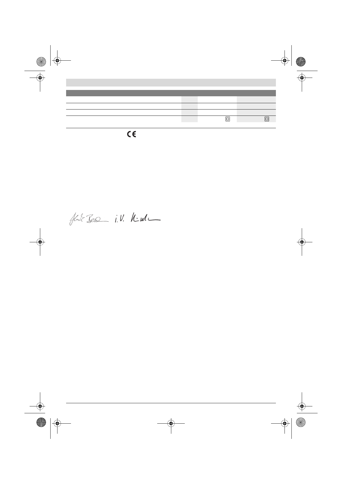
Declaration of Conformity
We declare under our sole responsibility that the product de-
scribed under “Technical Data” is in conformity with all rele-
vant provisions of the directives 2011/65/EU, until
19 April 2016: 2004/108/EC, from 20 April 2016 on:
2014/30/EU, 2006/42/EC including their amendments and
complies with the following standards: EN 60745-1,
EN 60745-2-5, EN 50581.
Technical file (2006/42/EC) at:
Robert Bosch Power Tools GmbH, PT/ETM9,
70538 Stuttgart, GERMANY
Robert Bosch Power Tools GmbH
70538 Stuttgart, GERMANY
Stuttgart, 01.01.2017
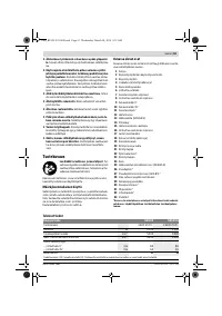
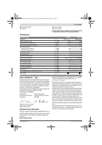
Noise/Vibration Information
Sound emission values determined according to
EN 60745-2-5.
Typically the A-weighted noise levels of the product are:
Sound pressure level 92 dB(A); Sound power level
103 dB(A). Uncertainty K = 3 dB.
Wear hearing protection!
Vibration total values a
h
(triax vector sum) and uncertainty K
determined according to EN 60745-2-5:
a
h
= 3.0 m/s
2
, K = 1.5 m/s
2
.
The vibration level given in this information sheet has been
measured in accordance with a standardised test given in
EN 60745 and may be used to compare one tool with anoth-
er. It may be used for a preliminary assessment of exposure.
The declared vibration emission level represents the main ap-
plications of the tool. However if the tool is used for different
applications, with different accessories or insertion tools or is
poorly maintained, the vibration emission may differ. This
may significantly increase the exposure level over the total
working period.
An estimation of the level of exposure to vibration should also
take into account the times when the tool is switched off or
when it is running but not actually doing the job. This may sig-
nificantly reduce the exposure level over the total working
period.
Identify additional safety measures to protect the operator
from the effects of vibration such as: maintain the tool and the
accessories, keep the hands warm, organisation of work pat-
terns.
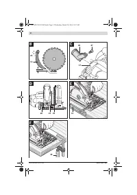
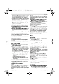
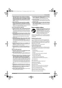
Assembly
Mounting/Replacing the Saw Blade
Before any work on the machine itself, pull the mains
plug.
When mounting the saw blade, wear protective gloves.
Danger of injury when touching the saw blade.
Only use saw blades that correspond with the charac-
teristic data given in the operating instructions.
Do not under any circumstances use grinding discs as
the cutting tool.
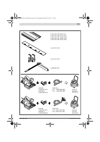
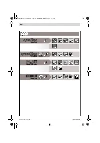
Selecting a Saw Blade
An overview of recommended saw blades can be found at the
end of this manual.
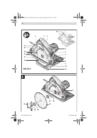
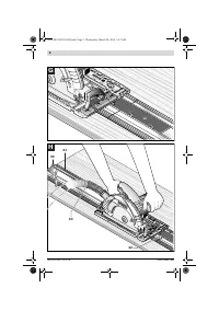
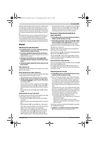
Removal of the Saw Blade (see figure A)
For changing the cutting tool, it is best to place the machine
on the face side of the motor housing.
– Press the spindle lock button
5
and keep it pressed.
The spindle lock button 5 may be actuated only when
the saw spindle is at a standstill.
Otherwise, the power
tool can be damaged.
– With the Hex key
19
, unscrew the clamping bolt
20
turning
in rotation direction
.
– Tilt back the retracting blade guard
12
and hold firmly.
– Remove the clamping flange
21
and the saw blade
22
from
the saw spindle
24
.
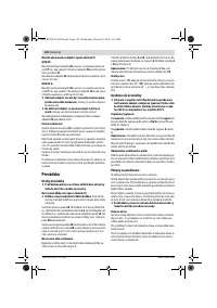
Mounting the Saw Blade (see figure A)
For changing the cutting tool, it is best to place the machine
on the face side of the motor housing.
– Clean the saw blade
22
and all clamping parts to be assem-
bled.
– Tilt back the retracting blade guard
12
and hold firmly.
– Place the saw blade
22
on to the mounting flange
23
. The
cutting direction of the teeth (direction or arrow on saw
blade) and the direction-of-rotation arrow on the blade
guard
1
must correspond.
– Mount the clamping flange
21
and screw in the clamping
bolt
20
turning in rotation direction
. Observe correct
mounting position of mounting flange
23
and clamping
flange
21
.
– Press the spindle lock button
5
and keep it pressed.
– With the Hex key
19
, tighten the clamping bolt
20
turning
in rotation direction
. The tightening torque is between
10 – 12 Nm, which corresponds to hand tight plus ¼ turn.
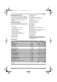
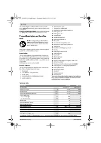
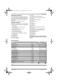
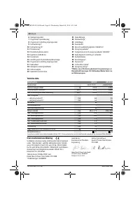
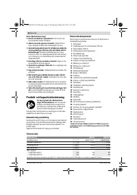
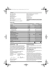
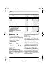
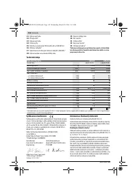
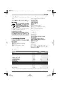
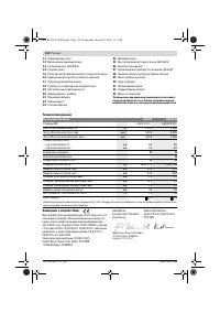
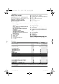
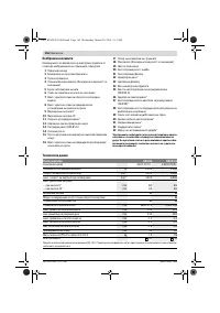
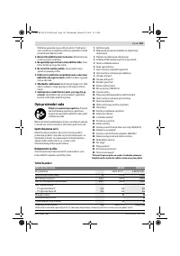
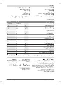
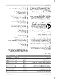
Tooth thickness/setting, min.
mm
2.0
2.0
Mounting bore
mm
30
30
Weight according to EPTA-Procedure 01:2014
kg
7.5
7.8
Protection class
/
II
/
II
Circular Saw
GKS 85
GKS 85 G
The values given are valid for a nominal voltage [U] of 230 V. For different voltages and models for specific countries, these values can vary.
Henk Becker
Executive Vice President
Engineering
Helmut Heinzelmann
Head of Product Certification
PT/ETM9
OBJ_BUCH-293-008.book Page 17 Wednesday, March 30, 2016 9:12 AM
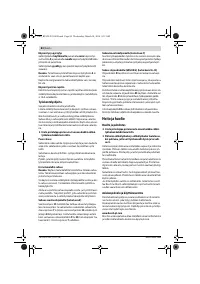
Содержание
- 133 Описание продукта и услуг; Применение по назначению
- 134 Технические данные
- 135 Данные по шуму и вибрации; Сборка; Установка/смена пильного диска
- 136 Отсос пыли и стружки; Работа с инструментом; Режимы работы; Включение электроинструмента
- 137 Указания по применению; Техобслуживание и сервис; Техобслуживание и очистка
- 138 Утилизация
Характеристики

Остались вопросы?Не нашли свой ответ в руководстве или возникли другие проблемы? Задайте свой вопрос в форме ниже с подробным описанием вашей ситуации, чтобы другие люди и специалисты смогли дать на него ответ. Если вы знаете как решить проблему другого человека, пожалуйста, подскажите ему :)


