
Мультиметры BENNING MM 5-2 044071 - инструкция пользователя по применению, эксплуатации и установке на русском языке. Мы надеемся, она поможет вам решить возникшие у вас вопросы при эксплуатации техники.
Если остались вопросы, задайте их в комментариях после инструкции.
"Загружаем инструкцию", означает, что нужно подождать пока файл загрузится и можно будет его читать онлайн. Некоторые инструкции очень большие и время их появления зависит от вашей скорости интернета.


02/ 2020
BENNING MM 5-1/ 5-2
27
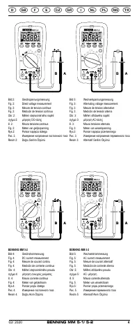
See fig. 5:
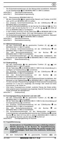
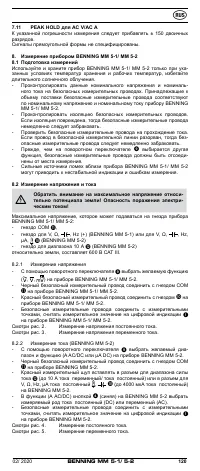
AC-current measurement
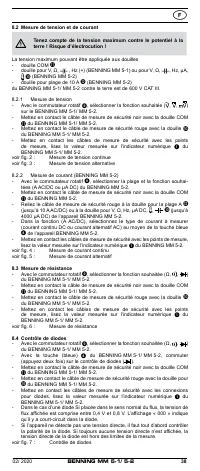
8.3 Resistance measurement
- With the rotating switch
, select the desired function (Ω,
,
) on the
BENNING MM 5-1/ MM 5-2.
- Connect the black safety measuring lead to the COM socket
on the
BENNING MM 5-1/ MM 5-2.
-
Connect the red safety measuring lead to the socket
on the
BENNING MM 5-1/ MM 5-2.
-
Connect the safety measuring leads to the measuring points. Read the measure-
ment value displayed in the digital display
of the BENNING MM 5-1/ MM 5-2.
See fig. 6:
Resistance measurement
8.4 Diode testing
- With the rotating switch
, select the desired function (Ω,
, ) on the
BENNING MM 5-1/ MM 5-2.
- Using the blue key
on the BENNING MM 5-1/ MM 5-2, switch to (press
twice) diode testing (
).
- Connect the black safety measuring lead to the COM socket
on the
BENNING MM 5-1/ MM 5-2.
-
Connect the red safety measuring lead to the socket
on the
BENNING MM 5-1/ MM 5-2.
-
Contact the diode connections with the safety measuring leads and
read the measurement value displayed in the digital display
of the
BENNING MM 5-1/ MM 5-2.
- For a normal silicone diode located in flow direction, the flow voltage
between 0.4 V and 0.8 V is displayed. If “000” appears in the display, there
may be a short circuit in the diode.
- If no forward voltage is detected, first check the polarity of the diode. If still
no forward voltage is displayed, the forward voltage of the diode is beyond
the measuring limits.
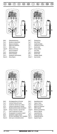
See fig. 7:
Diode testing
8.5 Continuity testing with buzzer and red LED
- With the rotating switch
, select the desired function (Ω,
,
) on the
BENNING MM 5-1/ MM 5-2.
- Using the blue key
4
on the BENNING MM 5-1/ MM 5-2, switch to continuity
testing ( ).
- Connect the black safety measuring lead to the COM socket
on the
BENNING MM 5-1/ MM 5-2.
-
Connect the red safety measuring lead to the socket
on the
BENNING MM 5-1/ MM 5-2.
- Contact the measuring points with the safety measuring leads. If the line
resistance between the COM jack
and the jack
falls below 30 Ω to
200 Ω, the integrated buzzer of the BENNING MM 5-1/ MM 5-2 sounds and
the red LED
N
lights up.
See fig. 8:
Continuity testing with buzzer
8.6 Capacitance measurement
Discharge capacitors fully before measurement! Never apply
voltage to the sockets for capacitance measurement as this
may cause irreparable damage to the unit. A damaged unit may
represent an electrical hazard!
- With the rotating switch
, select the desired function (
) on the
BENNING MM 5-1/ MM 5-2.
- Determine the polarity of the capacitor and discharge it completely.
- Connect the black safety measuring lead to the COM socket
on the
BENNING MM 5-1/ MM 5-2.
-
Connect the red safety measuring lead to the socket
on the
BENNING MM 5-1/ MM 5-2.
- Contact the discharged capacitor with the safety measuring leads observing
correct polarity. Read the measurement value on the digital display
of the
BENNING MM 5-1/ MM 5-2.
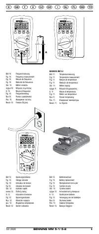
See fig. 9:
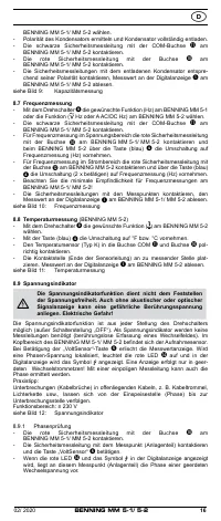
Capacity measurement
8.7 Frequency measurement
- Use the rotary switch
9
to select the desired function (Hz) of the
BENNING MM 5-1 or the function ( Hz or A AC/DC Hz) of the
BENNING MM 5-2.
- Connect the black safety measuring lead to the COM socket
on the
BENNING MM 5-1/ MM 5-2.
- For frequency measurement in the voltage range, connect the red safety


