
Мультиметры BENNING MM 4 044073 - инструкция пользователя по применению, эксплуатации и установке на русском языке. Мы надеемся, она поможет вам решить возникшие у вас вопросы при эксплуатации техники.
Если остались вопросы, задайте их в комментариях после инструкции.
"Загружаем инструкцию", означает, что нужно подождать пока файл загрузится и можно будет его читать онлайн. Некоторые инструкции очень большие и время их появления зависит от вашей скорости интернета.


05/ 2019
BENNING MM 4
14
test lead is interrupted, discard the safety test lead immediately.
- Before selecting another function at the sliding switch
2
or function button
4
, the safety test lead and red test probes must first be disconnected from
the measurement point.
- Strong sources of interference in the vicinity of the BENNING MM 4 may
cause unstable or incorrect readings.
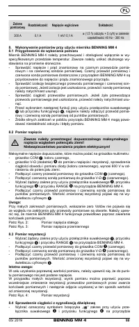
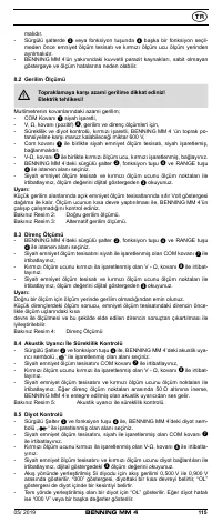
8.2 Voltage measurement
Always observe the maximum voltage to earth potential!
Electrical hazard!
The maximum voltage which may be applied to the sockets of the Multimeter with
-
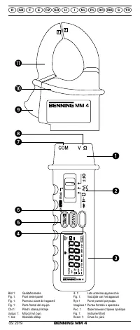
COM socket
7
, marked black,
- V-Ω socket (positive)
8
for voltage and resistance measurements, continu-
ity and diode testing (marked red) of the BENNING MM 4 with reference to
earth potential is 600 V.
- Plug the black safety test lead into the COM socket
7
(black).
- Plug the red test probe into the V-Ω socket
8
(red).
- With the slide switch
2
, the function button
4
and the RANGE button
6
of
the BENNING MM 4, select the desired range.
- Contact the measurement points with the black safety test lead and the red
test probe. The measured value appears in the digital display
3
.
Note:
In low voltage ranges, the zero volts display does not appear due to interference
when the safety test leads are open. Check that the BENNING MM 4 is fully
functional by short-circuiting the test probe.
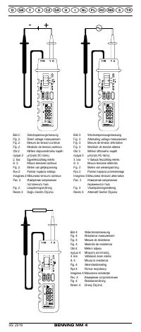
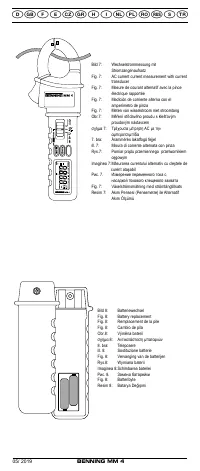
See fig. 2:
DC-voltage measurement
See fig. 3:
AC-voltage measurement
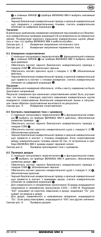
8.3 Resistance measurement
- With the slide switch
2
, the function button
4
and the RANGE button
6
of
the BENNING MM 4, select the desired range.
- Plug the black safety test lead into the COM socket
7
(black).
- Plug the red test probe into the V-Ω socket
8
(red).
- Contact the measurement points with the black safety test lead and the red
test probe. The measured value appears in the digital display
3
.
Important:
To obtain accurate measurements, ensure that no voltage is applied to the
measuring point.
With smaller resistances, the result can be improved by measuring the resist-
ance of the safety test lead beforehand by short-circuiting the test probe and
subtracting this resistance figure from the result.
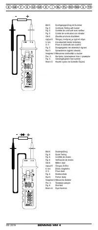
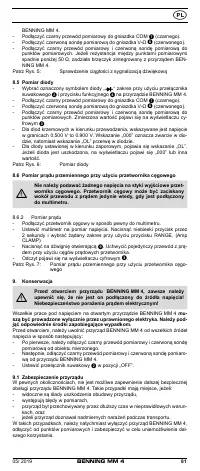
See fig. 4:
Resistance measurement
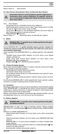
8.4 Continuity test with buzzer
- With the slide switch
2
and the function button
4
select the range marked
with the buzzer symbol „ “ on the BENNING MM 4.
- Plug the black safety test lead into the COM socket
7
(black).
- Plug the red test probe into the V-Ω socket
8
(red).
- Contact the measurement points with the black safety test lead and the red
test probe. When the resistance between the measuring points drops below
50 Ω, the buzzer integrated in the BENNING MM 4 sounds.
See fig. 5:
Continuity test with buzzer
8.5 Diode testing
- With the slide switch
2
and the function button
4
select the range marked
with the diode symbol „
“ on the BENNING MM 4.
- Plug the black safety test lead into the COM socket
7
(black).
- Plug the red test probe into the V-Ω socket
8
(red).
- Contact the diode connections with the black safety test lead and the red test
probe. The value measured appears in the digital display
3
.
- For Si diodes located in conducting direction, the flow voltage of 0.500 V to
0.900 V is indicated. The reading “000” indicates a short circuit in the diode,
and the reading “OL” an interruption in the diode.
- For a diode located in the non-conducting direction “OL” appears. If the
diode is defective, “000” or other figures appear.
See fig. 6:
Diode testing


