Мойки высокого давления Karcher HDS 13 24 PE Cage - инструкция пользователя по применению, эксплуатации и установке на русском языке. Мы надеемся, она поможет вам решить возникшие у вас вопросы при эксплуатации техники.
Если остались вопросы, задайте их в комментариях после инструкции.
"Загружаем инструкцию", означает, что нужно подождать пока файл загрузится и можно будет его читать онлайн. Некоторые инструкции очень большие и время их появления зависит от вашей скорости интернета.


20
English
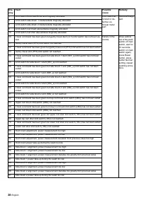
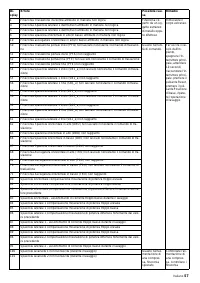
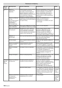
Shampoo from the jets for brush watering
mixed as detergent with water is sprayed on
the vehicle.
The foam wash sprays the vehicle with
foam before the wash.
The dirt catcher retains particles which
could block the jets.
The dosing pumps mixes the following de-
tergents and cleaning products with water:
– shampoo, foam, (DT 811)
– hot wax, (DT 829)
– drying aid, (DT 829).
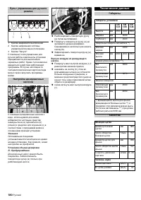
The air needed for to blow-dry the vehicle
sides flows out of the drier jets.
The blow-dry beam is moved along the con-
tour of the vehicle. Built-in ventilators gen-
erate the necessary air flow to dry the
vehicle.
The vehicle positioning traffic light has two
functions:
– It is used to position the vehicle before
the wash.
– The drive-out direction is indicated after
the wash.
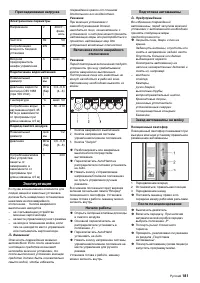
The light barriers detect:
– the position and contours of the vehicle
and
the position of the wheels.
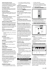
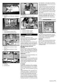
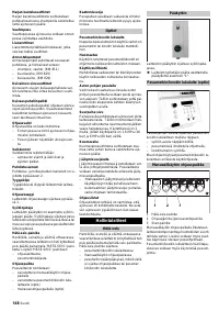
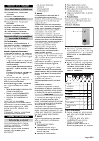
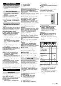
The canisters for detergents and care-liquid
are installed in the pillar 2.
The important plant data on the nameplate.
The control cabinet for the plant is accomo-
dated in column 1.
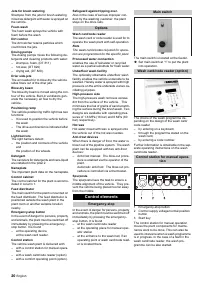
The main switch for the plant is mounted on
the feed distributor. The feed distributor is
positioned outside the wash plant in the
plant room or another suitable location
nearby.
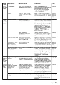
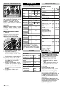
In the event of danger for persons, property
and animals, the plant must be switched off
immediately by pressing the emergency-
stop button. It is found
– at the operating device,
at the wash card reader.
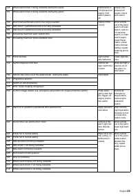
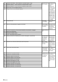
The vehicle wash plant is delivered with:
– with a control station for manual opera-
tion
– with a wash card/code reader (option)
– with a comfort operating point (option).
Also in the case of serious improper con-
duct by the washing customer, the plant
stays on the drive-rails.
The wash card or code reader is used for to
operate the wash plant with self-operation.
Note
The wash cards/codes required for opera-
tion are programmed for the specific plant.
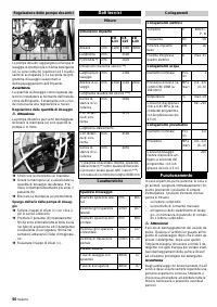
enables the use of rainwater or recycled
water as a partial substitute for fresh water.
The optionally obtainable underfloor wash
facility enables the vehicle underside to be
washed. Hereby water is sprayed with high
pressure on the entire underside via two os-
cillating jet pipes.
The high-pressure wash removes excess
dirt from the surface of the vehicle. This
minimises the risk of grains of sand scratch-
ing the surface during the brush wash. Two
designs are available with operating pres-
sures of 1.6 MPa (16 bar) and 6 MPa (60
bar) respectively.
Hot water mixed with wax is sprayed onto
the vehicle out of the hot wax nozzles.
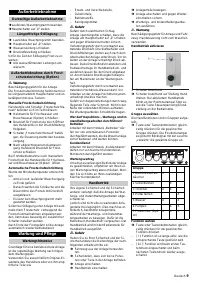
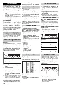
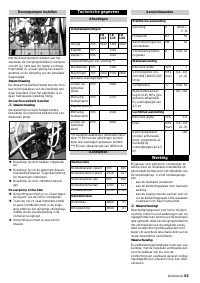
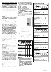
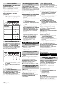
When there is danger of frost, the water is
blown out of the pipeline system. The wash
plant can be equipped with two anti-frost
devices:
– Anti-frost manual: The blow-out proce-
dure is enabled via the operator of the
plant.
Automatic anti-frost: The blow-out pro-
cedure is controlled via a thermostat.
The spurposts have the task to ensure a
middle alignment of the vehicle. They pre-
vent the vehicle being placed too far away
from the middle.
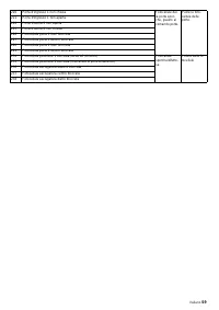
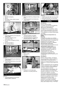
In the event of danger for persons, property
and animals, the plant must be switched off
immediately by pressing the emergency-
stop button. It is found
– at the wash card/code reader
– at the operating place for manual oper-
ator station
– at the entrance to the wash hall, íf an
operating point or wash card/code read-
er is located there.
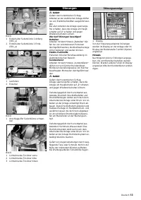
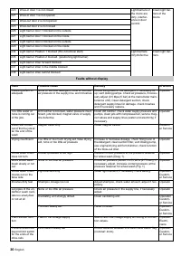
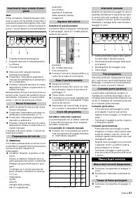
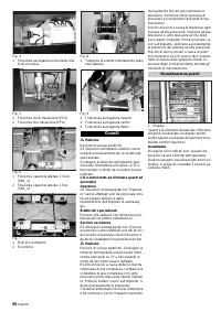
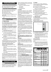
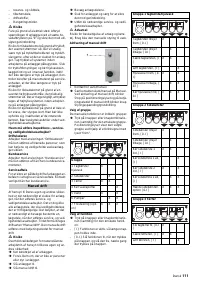
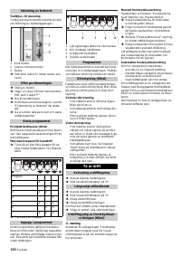
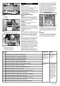
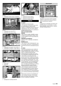
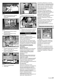
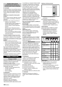
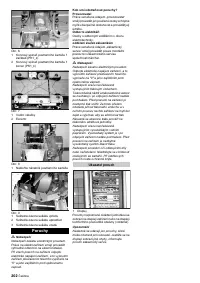
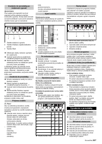
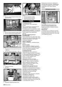
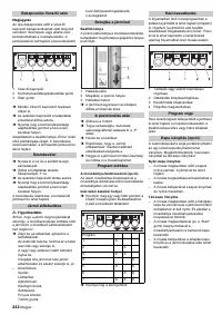
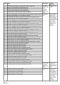
The main switch is located at the feeder.
Î
Set main switch at “1” to put the plant
into operation.
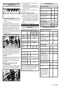
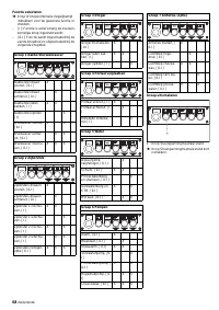
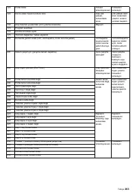
The choice of the wash programme de-
pending on the design of the wash card/
code reader
– by entering on a keyboard,
– through the programme stated on the
wash card,
– by entering a code number.
Further information is obtainable in the sep-
arate operating instructions on the wash
card/code reader.
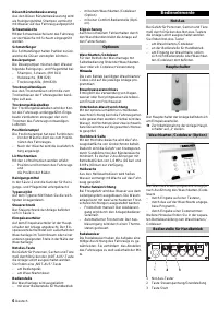
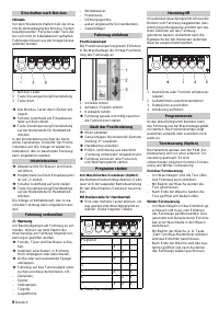
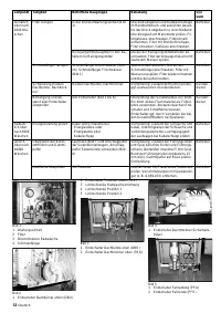
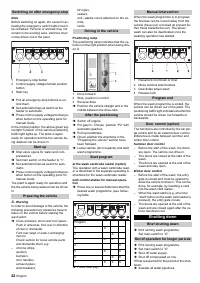
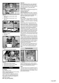
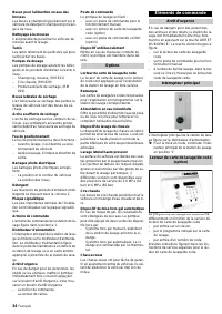
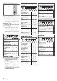
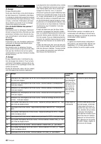
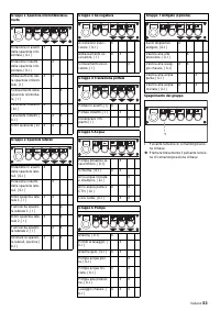
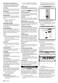
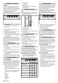
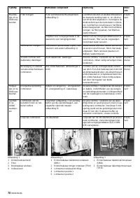
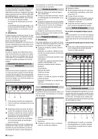
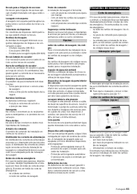
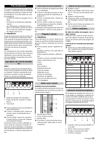
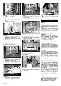
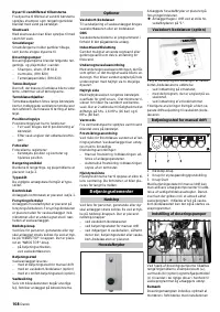
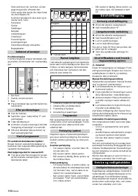
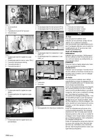
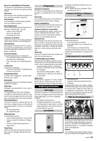
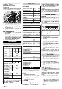
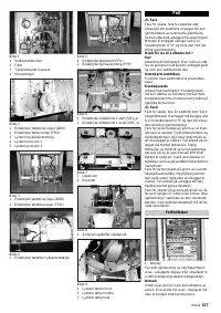
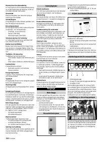
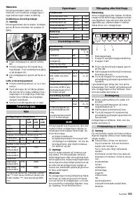
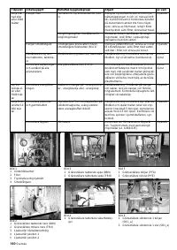
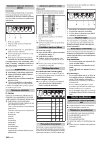
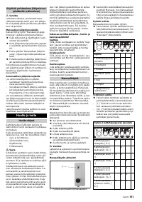
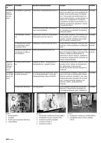
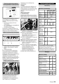
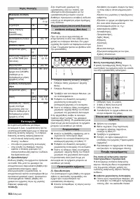
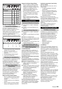
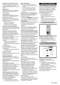
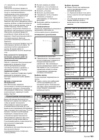
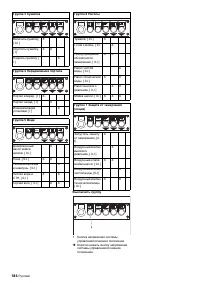
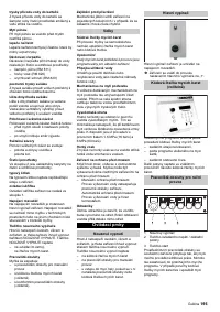
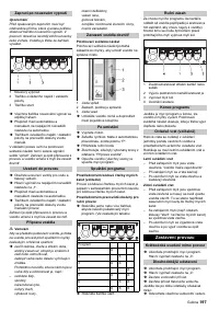
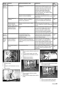
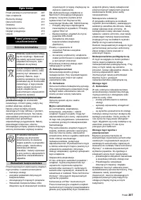
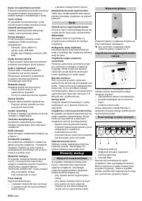
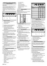
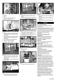
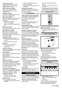
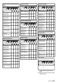
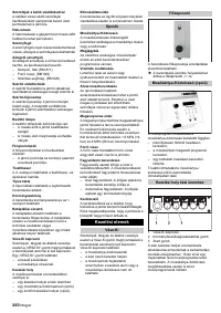
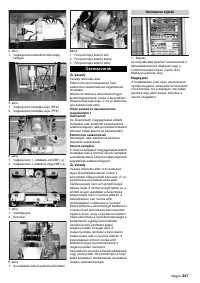
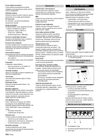
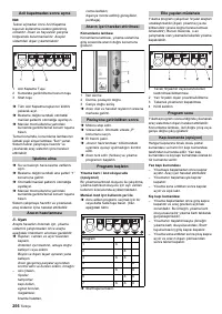
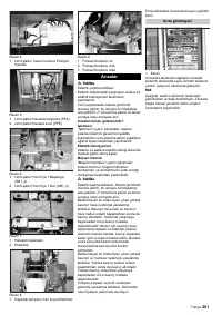
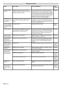
1 Emergency-stop button
2 Control supply voltage/normal position
button
3 Start key
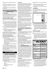
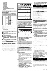
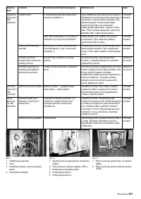
The control station for manual operation
moves the plant components for mainte-
nance work to be done. This can also be
used to intervene when a wash programme
is in progress. In the case of a fault in the
wash card/code reader, the wash pro-
gramme can be also started.
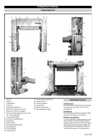
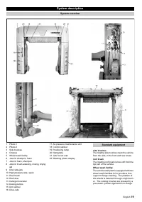
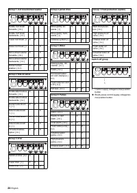
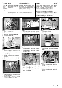
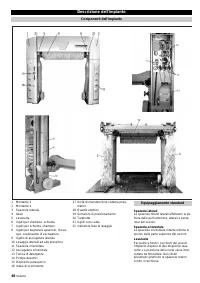
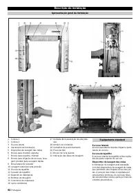
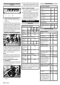
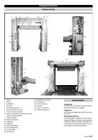
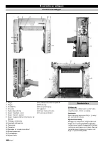
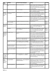
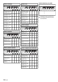
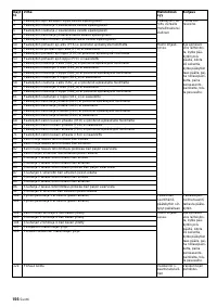
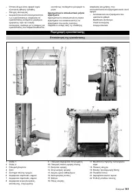
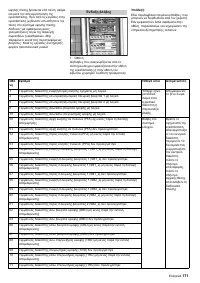
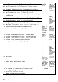
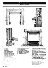
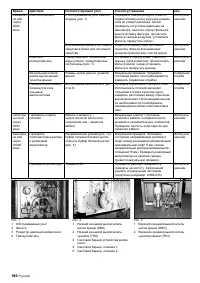
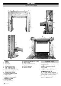
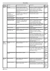
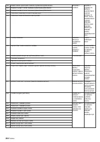
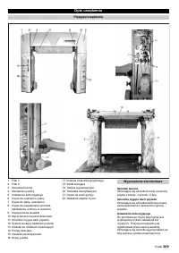
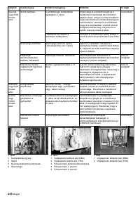
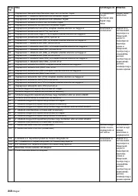
Jets for brush watering
Foam wash
Dirt catcher
Dosing pumps
Drier side-jets
Blow-dry beam
Positioning ramp
Light barriers
Detergent
Nameplate
Control cabinet
Feed distributor
Emergency-stop button
Control station
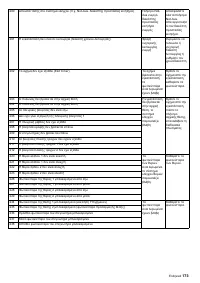
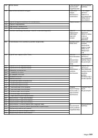
Safeguard against tipping over.
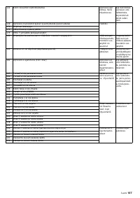
Options
Wash card/code reader
Processed water connection
Underfloor wash facility
High-pressure side
Hot wax
Anti-frost devices
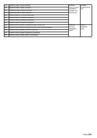
Spurposts
Control elements
Emergency-stop
Main switch
Wash card/code reader (option)
Control station for manual opera-
tion


