Материнские платы GIGABYTE GA 8I945GMMFY RH - инструкция пользователя по применению, эксплуатации и установке на русском языке. Мы надеемся, она поможет вам решить возникшие у вас вопросы при эксплуатации техники.
Если остались вопросы, задайте их в комментариях после инструкции.
"Загружаем инструкцию", означает, что нужно подождать пока файл загрузится и можно будет его читать онлайн. Некоторые инструкции очень большие и время их появления зависит от вашей скорости интернета.
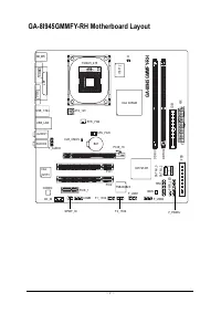


GA-8I945GMMFY-RH Motherboard
- 22 -
English
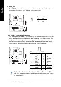
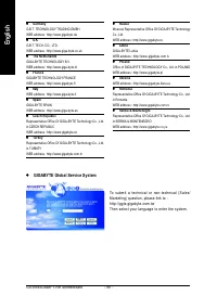
9) PWR_LED
The PWR_LED connector is connected with the system power indicator to indicate whether the
system is on/off. It will blink when the system enters suspend mode.
Pin No.
Definition
1
MPD+
2
MPD-
3
MPD-
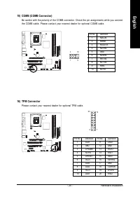
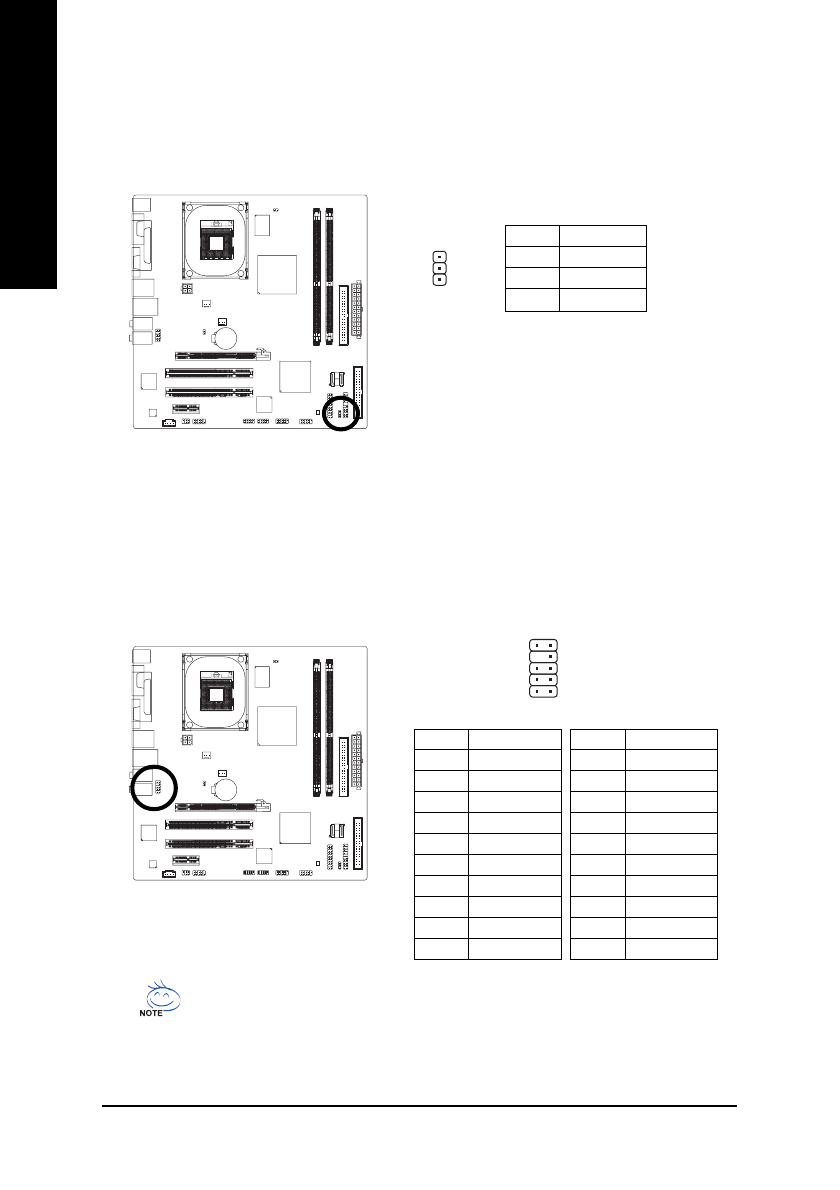
10) F_AUDIO (Front Audio Panel Connector)
This connector supports either HD (High Definition) or AC97 front panel audio module. If you wish
to use the front audio function, connect the front panel audio module to this connector. Check the pin
assignments carefully while you connect the front panel audio module. Incorrect connection
between the module and connector will make the audio device unable to work or even damage it.
For optional front panel audio module, please contact your chassis manufacturer.
1
9
1 0
1
2
Pin No.
Definition
1
MIC2_L
2
GND
3
MIC2_R
4
-ACZ_DET
5
Line2_R
6
FSENSE1
7
FAUDIO_JD
8
No Pin
9
LINE2_L
10
FSENSE2
Pin No.
Definition
1
MIC
2
GND
3
MIC Power
4
NC
5
Line Out (R)
6
NC
7
NC
8
No Pin
9
Line Out (L)
10
NC
HD Audio:
AC'97 Audio:
By default, the audio driver is configured to support HD Audio. To connect an AC97 front
panel audio module to this connector, please refer to the instructions on Page 74 about
the software settings.


