Материнские платы GIGABYTE B660 - инструкция пользователя по применению, эксплуатации и установке на русском языке. Мы надеемся, она поможет вам решить возникшие у вас вопросы при эксплуатации техники.
Если остались вопросы, задайте их в комментариях после инструкции.
"Загружаем инструкцию", означает, что нужно подождать пока файл загрузится и можно будет его читать онлайн. Некоторые инструкции очень большие и время их появления зависит от вашей скорости интернета.


- 22 -
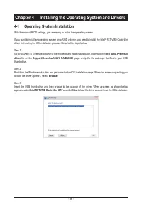
•
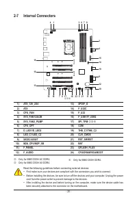
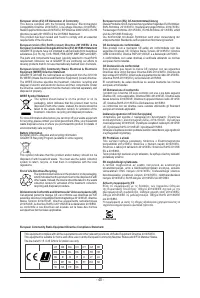
Be sure to connect fan cables to the fan headers to prevent your CPU and system from
overheating. Overheating may result in damage to the CPU or the system may hang.
•
These fan headers are not configuration jumper blocks. Do not place a jumper cap on the headers.
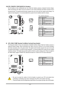
3/4) CPU_FAN/SYS_FAN1/2A/2B (Fan Headers)
All fan headers on this motherboard are 4-pin. Most fan headers possess a foolproof insertion design.
When connecting a fan cable, be sure to connect it in the correct orientation (the black connector wire is
the ground wire). The speed control function requires the use of a fan with fan speed control design. For
optimum heat dissipation, it is recommended that a system fan be installed inside the chassis.
CPU_FAN
SYS_FAN1
DEBUG
PORT
G.QBOFM
1
SYS_FAN2A/
SYS_FAN2B
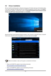
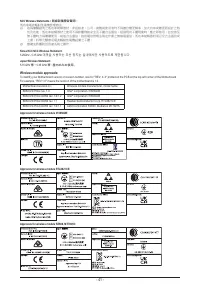
5) SYS_FAN3_PUMP (System Fan/Water Cooling Pump Header)
The fan/pump header is 4-pin and possesses a foolproof insertion design. Most fan headers possess a
foolproof insertion design. When connecting a fan cable, be sure to connect it in the correct orientation
(the black connector wire is the ground wire). The speed control function requires the use of a fan with
fan speed control design. For optimum heat dissipation, it is recommended that a system fan be installed
inside the chassis. The header also provides speed control for a water cooling pump. Please navigate to
the "BIOS Setup" page of GIGABYTE's website and search for "Smart Fan 6" for more information.
Pin No.
Definition
1
GND
2
Voltage Speed Control
3
Sense
4
PWM Speed Control
DEBUG
PORT
G.QBOFM
1
DEBUG
PORT
G.QBOFM
1
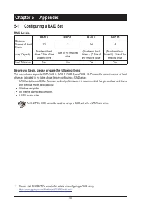
CPU_FAN/SYS_FAN1/2A:
Pin No.
Definition
1
GND
2
Voltage Speed Control
3
Sense
4
PWM Speed Control
SYS_FAN2B:
Pin No.
Definition
1
GND
2
Voltage Speed Control
3
Sense
4
NC
Характеристики

Остались вопросы?Не нашли свой ответ в руководстве или возникли другие проблемы? Задайте свой вопрос в форме ниже с подробным описанием вашей ситуации, чтобы другие люди и специалисты смогли дать на него ответ. Если вы знаете как решить проблему другого человека, пожалуйста, подскажите ему :)


