Лобзики Graphite 58G011 - инструкция пользователя по применению, эксплуатации и установке на русском языке. Мы надеемся, она поможет вам решить возникшие у вас вопросы при эксплуатации техники.
Если остались вопросы, задайте их в комментариях после инструкции.
"Загружаем инструкцию", означает, что нужно подождать пока файл загрузится и можно будет его читать онлайн. Некоторые инструкции очень большие и время их появления зависит от вашей скорости интернета.


14
When the batter y (
13
) is placed in the charger (
14
), the red diode
(
15
) on the charger turns on to indicate that the charging is in
progress.
At the same time green diodes (
17
) of the batter y level indication
are flashing in different configurations, see description below.
• All diodes are flashing
- batter y is empty and requires
charging.
• 2 diodes are flashing
- the batter y is par tially discharged.
• 1 diode is flashing
- the batter y level is high.
Once the batter y is charged, the diode (
15
) on the charger lights
green, and all batter y level diodes (
17
) light continuously. After
some time (approx. 15 s) batter y level indication diodes (
17
) turn
off.
Do not charge the batter y for more than 8 hours. Exceeding
this time limit may cause damage to batter y cells. The charger
will not turn off automatically when the batter y is full. Green
diode on the charger will remain on. Batter y level indication
diodes turn off after some time. Disconnect power supply
before removing the batter y from the charger socket. Avoid
consecutive shor t chargings. Do not charge the batter y after
shor t use of the tool. Significant decrease of the period
between chargings indicates the batter y is worn out up and
should be replaced.
Batteries heat up when charging. Do not operate just
after charging – wait for the batter y to cool down to room
temperature. It will prevent batter y damage.
BAT TERY LE VEL INDIC ATION
The batter y is equipped with signalisation of the batter y level (3
LED diodes) (
17
). To check batter y level status, press the button
for batter y level indication (
13
) (
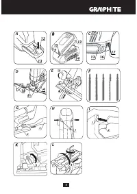
fig. C
). When all diodes are lit,
the batter y level is high. When 2 diodes are on, the batter y is
par tially discharged. When only one diode is lit, the batter y is
discharged and must be recharged.
INSTALLATION OF THE EDGE GUIDE
Edge guide can be installed on left or right side of the device
footplate.
•
Loosen the edge guide locking screws (
8
).
•
Slide the edge guide bar (
18
) into holes in the footplate (
4
), use
the scale to set required distance and fix by tightening the edge
guide locking screws (
8
) (
fig. D
).
Edge guide bar should be pointed downwards.
The edge guide (
18
) can also be used for bevel cutting at angles
ranging from 0° to 45°.
BLADE INSTALLATION
Installation and removal of the blade is tool free.
Blade installation
•
Set the switch for pendulum action (
5
) to position “
III
” and lift the
guard (
10
).
•
Slide blade to the blade holder (
6
) to mechanical stop (blade teeth
should face forward) (
fig. E
).
Important!
Make sure the blade is properly positioned in the
guiding roller (
7
).
Blade removal
•
Set the switch for pendulum action (
5
) to position “
III
” and lift the
guard (
10
).
•
Pull lever of the blade holder (
6
) upwards and slide the blade out
(
fig. E
).
•
Release the blade holder lever (
7
).
Use blades suitable for T-shank holder mechanism, as shown on
fig. F.
DUST EXTRACTION
To improve dust extraction from processed material surface, the
jigsaw is equipped with own dust blow-off and extraction system,
which cleans the surface being cut. Dust blow-off and extraction
system is more efficient when the guard is lowered.
•
Insert the adapter (
3
) fully into the footplate (
4
) (
fig. G
).
•
Attach suction hose of the dust extraction system to the adapter
(
3
).
•
Adapter removal is similar to installation, only the sequence of
actions is reversed.
OPERATION / SETTINGS
SWITCHING ON / SWITCHING OFF
The device is equipped with the switch lock button (
1
) that protects
against accidental start up. The safety switch is located on both sides
of the tool body.
Switching on
•
Press one end of the switch lock button (
1
) and hold (
fig. H
).
•
Press the switch button (
2
) (
fig. I
).
•
You can release the switch lock button (
1
) after starting the device.
Switching off
•
Release pressure on the switch button (
2
) to stop the tool.
Device speed within its range is controlled with pressure on the
switch button.
Each time the switch button (
2
) is pressed, the LED diode (
11
) lights
up to illuminate the workplace.
BLADE PENDULUM ACTION CONTROL
Besides reciprocating movement control there is also possibility
to set blade pendulum action level. It allows for better adjustment
of the tool operation parameters to type of processed material.
Pendulum action is controlled in steps with the switch for pendulum
action setting (
5
) and its range is
0
to
3
(
fig. K
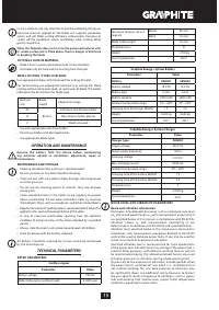
). The table below
presents the best choices of pendulum action setting for various
materials:
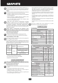
Metal sheet, in general: 0
Steel sheet: 0 – 1
Aluminium sheet: 1– 2
Plastics: 1 – 2
Plywood: 0 – 1
Wood: 1 - 3
Set the switch for pendulum action to 0 when using knife blade.
Lubrication is recommended for metal cutting.
FOOTPLATE ADJUSTMENT FOR BEVEL CUTTING
Adjustable jigsaw footplate allows to make a bevel cut in the range
from 0° to 45° (to either side).
•
Remove the adapter (
3
) from the footplate (
4
) (
fig. G
).
•
Use the hexagonal key and loosen the footplate (
4
) fixing screws.
•
Move the footplate (
4
) forward and tilt right or left (up to 45°).
•
Set the footplate (
4
) at desired angle, move backward and tighten
the fixing screw to secure it (
fig. L
).
Footplate angular scale allows for setting the footplate at angles:
0°, 15°, 30° or 45° (right or left). Always put the hexagonal key in its
storage place after adjustment has been made.
CUTTING
•
Place the front part of the footplate (
4
) flat on the material for
processing, so the blade does not have contact with the material.
•
Switch on the jigsaw and wait until it reaches its working speed.
•
Move the jigsaw slowly and guide the blade along previously set
cutting line.
•
When cutting curved lines move the jigsaw very carefully.
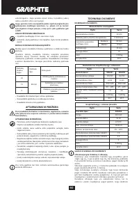
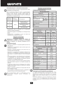
Характеристики

Остались вопросы?Не нашли свой ответ в руководстве или возникли другие проблемы? Задайте свой вопрос в форме ниже с подробным описанием вашей ситуации, чтобы другие люди и специалисты смогли дать на него ответ. Если вы знаете как решить проблему другого человека, пожалуйста, подскажите ему :)


