Лобзики Bosch GST 8000E - инструкция пользователя по применению, эксплуатации и установке на русском языке. Мы надеемся, она поможет вам решить возникшие у вас вопросы при эксплуатации техники.
Если остались вопросы, задайте их в комментариях после инструкции.
"Загружаем инструкцию", означает, что нужно подождать пока файл загрузится и можно будет его читать онлайн. Некоторые инструкции очень большие и время их появления зависит от вашей скорости интернета.


English |
13
Bosch Power Tools
1 609 92A 2GY | (3.6.16)
12
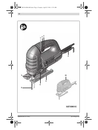
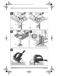
SDS clamping lever for saw blade release
13
Splinter guard
14
Scale for mitre angle
15
Screw
* Accessories shown or described are not part of the standard de-
livery scope of the product. A complete overview of accessories
can be found in our accessories program.
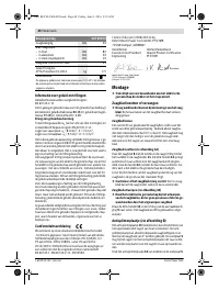
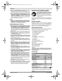
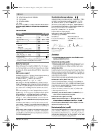
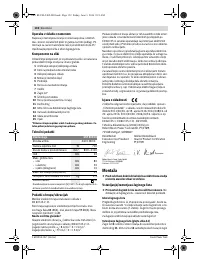
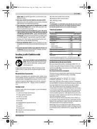
Technical Data
Noise/Vibration Information
Sound emission values determined according to
EN 60745-2-11.
Typically the A-weighted noise levels of the product are:
Sound pressure level 88 dB(A); Sound power level 99 dB(A).
Uncertainty K = 3 dB.
Wear hearing protection!
Vibration total values a
h
(triax vector sum) and uncertainty K
determined according to EN 60745-2-11:
Sawing chipboard: a
h
= 8.6 m/s
2
, K = 1.5 m/s
2
,
Sawing sheet metal: a
h
= 9.5 m/s
2
, K = 1.5 m/s
2
.
The vibration level given in this information sheet has been
measured in accordance with a standardised test given in
EN 60745 and may be used to compare one tool with anoth-
er. It may be used for a preliminary assessment of exposure.
The declared vibration emission level represents the main ap-
plications of the tool. However if the tool is used for different
applications, with different accessories or insertion tools or is
poorly maintained, the vibration emission may differ. This
may significantly increase the exposure level over the total
working period.
An estimation of the level of exposure to vibration should also
take into account the times when the tool is switched off or
when it is running but not actually doing the job. This may sig-
nificantly reduce the exposure level over the total working
period.
Identify additional safety measures to protect the operator
from the effects of vibration such as: maintain the tool and the
accessories, keep the hands warm, organisation of work pat-
terns.
Declaration of Conformity
We declare under our sole responsibility that the product de-
scribed under “Technical Data” is in conformity with all rele-
vant provisions of the directives 2011/65/EU, until
19 April 2016: 2004/108/EC, from 20 April 2016 on:
2014/30/EU, 2006/42/EC including their amendments and
complies with the following standards:
EN 60745-1, EN 60745-2-11, EN 50581.
Technical file (2006/42/EC) at:
Robert Bosch Power Tools GmbH, PT/ETM9,
70538 Stuttgart, GERMANY
Robert Bosch Power Tools GmbH
70538 Stuttgart, GERMANY
Stuttgart, 01.01.2017
Assembly
Before any work on the machine itself, pull the mains
plug.
Replacing/Inserting the Saw Blade
When mounting the saw blade, wear protective gloves.
Danger of injury when touching the saw blade.
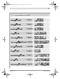
Selecting a Saw Blade
An overview of recommended saw blades can be found at the
end of these instructions. Use only T-shank saw blades. The
saw blade should not be longer than required for the intended
cut.
Use a thin saw blade for narrow curve cuts.
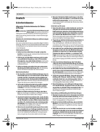
Inserting the Saw Blade (see figure A1)
Insert the saw blade
8
(teeth in cutting direction) into the
stroke rod
11
until it latches. The SDS lever
12
automatically
snaps to the rear and the saw blade is locked. Do not manually
press the lever
12
toward the rear, otherwise you could dam-
age the machine.
While inserting the saw blade, pay attention that the back of
the saw blade is positioned in the groove of the guide roller
7
.
Check the tight seating of the saw blade.
A loose saw
blade can fall out and lead to injuries.
Ejecting the Saw Blade (see figure A2)
When ejecting the saw blade, hold the machine in such
a manner that no persons or animals can be injured by
the ejected saw blade.
Turn the SDS lever
12
toward the front in the direction of the
contact protector
9
. The saw blade is released and ejected.
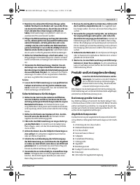
Splinter Guard (see figure B)
The splinter guard
13
(accessory) can prevent fraying of the
surface while sawing wood. The splinter guard can only be
used for certain saw blade types and only for cutting angles
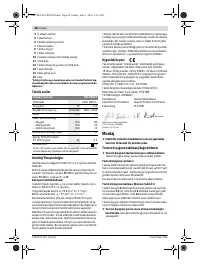
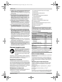
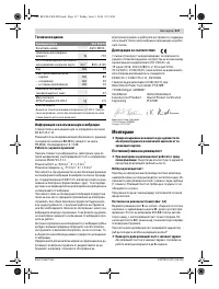
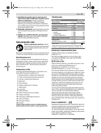
Jigsaw
GST 8000 E
Article number
3 601 E8H 0..
Rated power input
W
710
Stroke rate at no load n
0
min
-1
800 – 3 100
Stroke
mm
20
Cutting capacity, max.
– in wood
– in aluminium
– in non-alloy steel
mm
mm
mm
80
20
10
Bevel cuts (left/right), max.
°
45
Weight according to
EPTA-Procedure 01:2014
kg
2.5
Protection class
/
II
The values given are valid for a nominal voltage [U] of 230 V. For differ-
ent voltages and models for specific countries, these values can vary.
Henk Becker
Executive Vice President
Engineering
Helmut Heinzelmann
Head of Product Certification
PT/ETM9
OBJ_BUCH-2402-003.book Page 13 Friday, June 3, 2016 9:19 AM
Содержание
- 94 Описание продукта и услуг; Применение по назначению
- 95 Заявление о соответствии; Сборка; Установка/смена пильного полотна; Отсос пыли и стружки
- 96 Работа с инструментом; Режимы работы
- 97 Техобслуживание и сервис; Техобслуживание и очистка
- 98 Утилизация; Українська; Вказівки з техніки безпеки; Загальні застереження для електроприладів
Характеристики

Остались вопросы?Не нашли свой ответ в руководстве или возникли другие проблемы? Задайте свой вопрос в форме ниже с подробным описанием вашей ситуации, чтобы другие люди и специалисты смогли дать на него ответ. Если вы знаете как решить проблему другого человека, пожалуйста, подскажите ему :)


