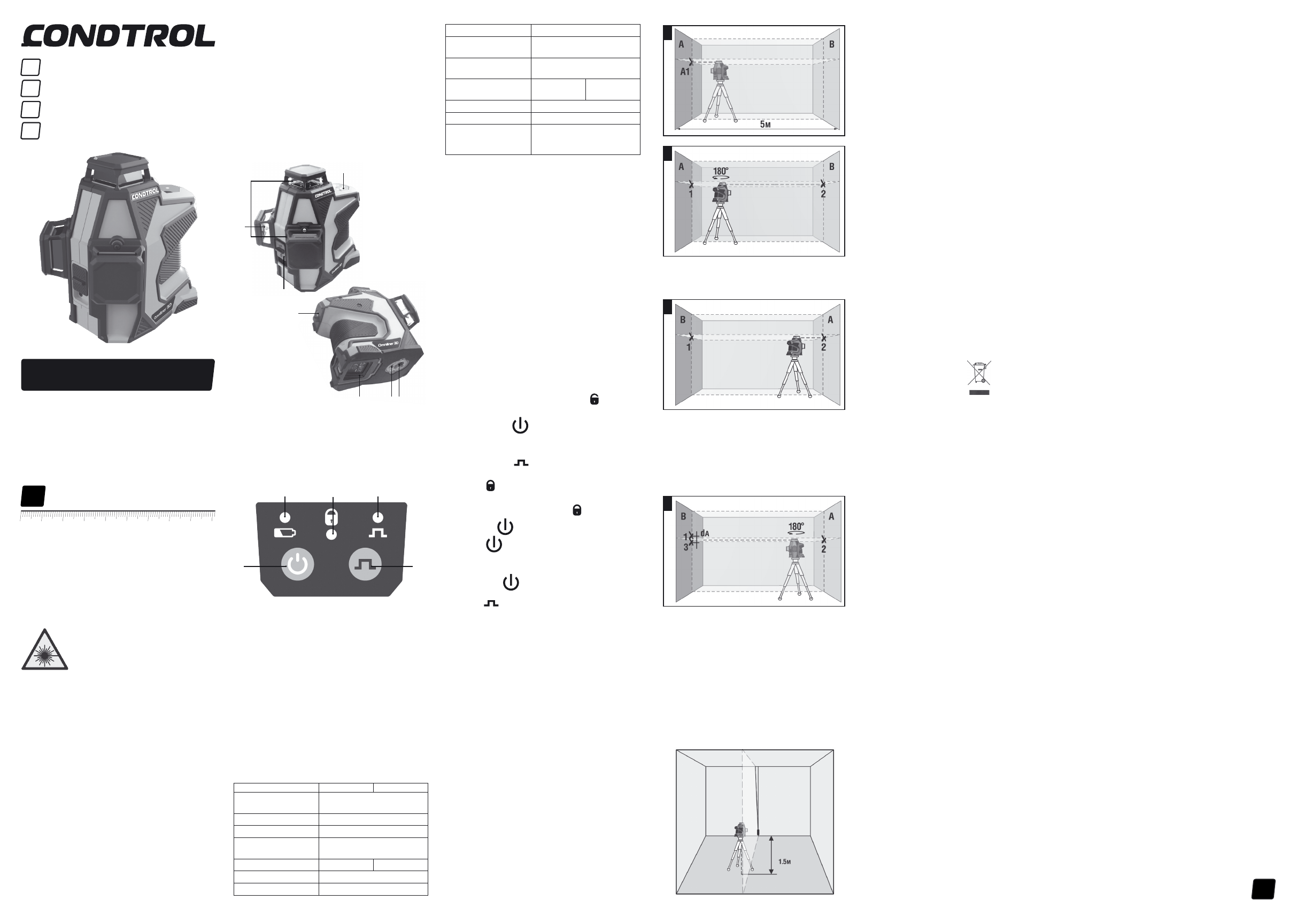
Измерительные приборы CONDTROL Omniliner G3D - инструкция пользователя по применению, эксплуатации и установке на русском языке. Мы надеемся, она поможет вам решить возникшие у вас вопросы при эксплуатации техники.
Если остались вопросы, задайте их в комментариях после инструкции.
"Загружаем инструкцию", означает, что нужно подождать пока файл загрузится и можно будет его читать онлайн. Некоторые инструкции очень большие и время их появления зависит от вашей скорости интернета.
1
EN User manual 1
DE Bedienungsanleitung 2
RU Руководство пользователя 3
PL
Instrukcja obsługi 4
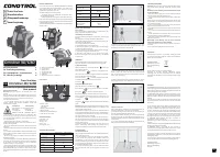
Omniliner 3D/G3D
User manual
Cross line laser
EN
SAFE T Y INSTRUC TIONS
Attention!
This user manual is an essential part of this
product.
The user manual should be read carefully before you use the
product for the first time. If the product is given to someone
for temporary use, be sure to enclose user manual to it.
- Do not misuse the product;
- Do not remove warning signs and protect them from
abrasion, because they contain information about safe
operation of the product.
- Do not look into the laser beam or its reflection, with
unprotected eye or through an optical instrument. Do not
point the laser beam at people or animals without the need.
You can dazzle them.
- To protect your eyes close them or look aside.
- Always install the product in such a way, so that laser line is
below or above eye level.
- Do not let unauthorized people enter the zone of product
operation.
- Store the product beyond reach of children and unauthorized
people.
- It is prohibited to disassemble or repair the product yourself.
Entrust product repair to qualified personnel and use original
spare parts only.
- Do not use the product in explosive environment, close to
flammable materials.
- Laser intensive glasses are used for better recognition of the
laser beam, do not use them for other purposes. Laser glasses
do not protect from laser radiation as well as ultraviolet
radiation and reduce color perception.
- Avoid heating the batteries to avoid the risk of explosion and
electrolyte leakage. In case of liquid contact with skin, wash
it immediately with soap and water. In case of contact with
eyes, flush with clean water during 10 minutes and consult the
doctor.
PRODUCT DESCRIPTION
CCross line lasers Omniliner 3D/G3D CONDTROL are intended
to project vertical and horizontal planes. They project one
360° horizontal and two 360° vertical planes and provide
compensation of the slope up to ±4°.
The laser levels have 2 operating modes:
- Automatic leveling to compensate irregularities within
self-leveling range of ± 4°;
- Locked compensator, to project inclined planes and lines.
Pulse mode allows using laser receiver to increase the working
range of the laser level or to work when laser is hard to define
in bright lighting conditions.
The laser levels are suitable for use at both indoor and outdoor
building areas.
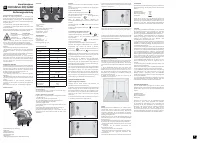
Omniliner 3D/G3D
6
1
2
3
4 5
1 - Laser lines exit window
2 – Control panel
3 – Battery cover
4 - Tripod thread 1/4’’
5 - Tripod thread 5/8’’
6 – Switch bar
7 – Hole for mounting on a screw/nail
Control panel
1. Switch on/off:
- The laser level
- laser lines
2. Switch on/off pulse mode
3. Power indicator
4. Indication of locked pendulum
5. Indication of pulse mode
DELIVERY PACKAGE
Laser level – 1 pc.
Battery – 2 pcs.
Charger – 1 pc.
Pouch – 1 pc.
User manual – 1 pc.
7
TECHNICAL SPECIFICATIONS
Omniliner 3D
Omniliner G3D
Working range/
with receiver
50 m/100 m
Self-levelling accuracy
±0,2 mm/m
Self-levelling range
± 4°
Self-leveling duration,
typically
<3″
Continuous working time
>10 hours
>5 hours
Working temperature
-10°C ... +50°C
Storage temperature
-20°C ... +70°C
OPERATION
Place the laser level on a firm and stable surface or a tripod.
Move the switch bar to select necessary operating mode:
1) Automatic leveling
Move the switch bar to unlocked position . H-line will
automatically switch on.
Short press button to switch on required laser lines.
If the laser level is out of the range of automatic compensation
laser lines will flash 1 time per second.
Short press button to switch on/off the pulse mode.
To switch off the laser level move the switch bar
to position .
2) Projection of inclined planes
Move the switch bar to locked position .
Press and hold during 3 seconds to switch on the laser.
Short press to switch on required laser lines.
Switched on laser lines will flash 1 time per each 5 seconds.
After all possible combinations of lines are switched on, the
next long press during 3 seconds will switch off the
laser level.
Long press during 3 seconds to switch on/off the pulse
mode.
Attention!
To increase the operating time and avoid the risk of
unintentional blindness switch the laser on only when you are
ready to make measurements.
If operated near objects or air streams with different from the
environment temperature the laser line may tremble due to
heterogeneity of the atmosphere. The longer is the distance,
the more trembling can be observed
The width of the laser line increases with the increasing of
the operating distance. The layout should be made along the
axis of the laser line. For maximum accuracy, use the middle
portion of the laser line.
It should be noted that the shape of the laser line on the
object’s surface (e.g., walls, ceilings, etc.) depends on the
curvature and tilt of the surface relative to the laser plane.
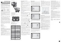
ACCURACY CHECK
Check of horizontal line
Use 2 parallel vertical walls which are located opposite each
other at a distance of 5 m.
1. Set the instrument close to the wall A (see Fig. A). Switch
on the vertical and horizontal laser emitters, unlock the
compensator. Turn the instrument in such a way so that the
laser lines intersecting each other are projected on the near
wall A opposite the instrument. Mark the point where laser
lines intersect each other as A1.
2. Turn the instrument by 180°, mark the point where laser
lines intersect each other on the opposite wall as В2. (see
Fig. В).
A
B
5. Measure distance d between points А1 and А3 (see. Fig. D).
If this distance exceeds 2 mm, please contact service center.
3. Move the instrument to the opposite wall B and set it in such
a way so that the point where laser lines intersect each other
would be on the same level with point B2.
C
D
Check of vertical line
Use a plumb bob as a reference of a vertical line. Place the
instrument at distance of 1,5m from the plumb bob.
1. Unlock the compensator, switch on the vertical laser line
and align it with the low point of plumb bob.
2. If deviation between the laser line and the plumb bob line
exceeds ±0.2 mm per 1 m of the plumb bob length (for a 2.5 m
plumb bob deviation shouldn’t exceed 0.5 mm) please contact
service center.
3. Turn the instrument by 180° and align the vertical laser line
with the low point of plumb bob once again.
4. Turn the instrument by 180°, direct the instrument to the
wall А in such a way so that the vertical line would coincide
with point А1. Mark the point of intersecting laser line on the
wall А as A3. (see. Fig. D).
CARE AND MAINTENANCE
Attention!
The product is an accurate optical mechanic device
and requires careful handling. Check the accuracy before
using.
Maintenance of the following recommendations will extend
the life of the device:
- Store the product, spare parts and its accessories beyond
reach of children and unauthorized people.
- The product should be transported only when compensator
is locked.
- Keep the product clean and protected from any bumps, dust
and dampness; do not allow getting moisture, dust or other
dirt inside of the product.
- In case if any moisture goes into the product, remove the
batteries and take it to the service center.
- Do not keep or use the device for a long time at high humidity
conditions.
- Carry out accuracy check regularly (see paragraph «Accuracy
check»).
- To clean the product use a soft wet cloth. Do not use harsh
chemicals, cleaning solvents or detergents.
- Сlean laser aperture periodically with a soft lint-free cloth
with isopropyl alcohol.
Mishandling of the following rules can cause electrolyte
leakage from the batteries or other damages:
- Remove the battery from the product if you do not use it for
a long time.
- Do not leave discharged battery in the laser level.
UTILIZATION
Expired tools, accessories and package should be passed
for waste recycle. Please send the product to the following
address for proper recycle:
CONDTROL GmbH
Wasserburger Strasse 9
84427 Sankt Wolfgang
Germany
Do not throw the product in municipal waste!
According to European directive 2002/96/ЕC expired
measuring tools and their components must be collected
separately and submitted to environmentally friendly recycle
of wastes.
WARRANTY
All CONDTROL GmbH products go through post-production
control and are governed by the following warranty terms. The
buyer’s right to claim about defects and general provisions of
the current legislation do not expire.
1) CONDTROL GmbH agrees to eliminate all defects in the
product, discovered while warranty period, that represent the
defect in material or workmanship in full volume and at its own
expense.
2) The warranty period is 24 months and starts from the date
of purchase by end consumer (see the original supporting
document).
3) The Warranty doesn’t cover defects resulting from wear
and tear or improper use, malfunction of the product caused
by failure to observe the instructions of this user manual,
untimely maintenance and service and insufficient care, the
use of non-original accessories and spare parts. Modifications
in design of the product relieve the seller from responsibility
for warranty works. The warranty does not cover cosmetic
damage, that doesn’t hinder normal operation of the product.
4) CONDTROL GmbH reserves the right to decide on
replacement or repair of the device.
5) Other claims not mentioned above, are not covered by the
warranty.
6) After holding warranty works by CONDTROL GmbH warranty
period is not renewed or extended.
7) CONDTROL GmbH is not liable for loss of profit or
inconvenience associated with a defect of the device, rental
cost of alternative equipment for the period of repair.
This warranty applies to German law except provision of the
United Nations Convention on contracts for the international
sale of goods (CISG).
In warranty case please return the product to retail seller or
send it with description of defect to the following address:
CONDTROL GmbH
Wasserburger Strasse 9
84427 Sankt Wolfgang
Germany
Laser radiation! Do not stare into beam
Class 2 laser
<1 mW 635 nm
EN60825-1: 2007-03
Cross line laser
Kreuzlinienlaser
EN
DE
Лазерный нивелир
RU
Laser krzyżowy
PL
Class 2 laser
<1 mW 520 nm
EN60825-1: 2007-03
1
2
4
3
5
Relative humidity
<90%
Dust and water
protection rate
IP65
Thread for mounting
on a tripod
1/4’’, 5/8’’
Laser type
Class II 635 nm
< 1 mW
Class II 520 nm
< 1 mW
Battery
3.7V 5200 mAh Li-ion
Dimensions
140х138х110 mm
Weight
- without battery
- with battery
660 g
774 g
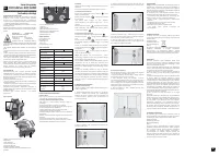
BEFORE START OPERATION
Power supply
The cross line laser is powered via a 3.7V 5200 mAh Li-ion
battery included in the delivery package.
Install/charge the Li-ion battery
Install the battery in the battery compartment, observing the
polarity.
Use the battery included in the delivery package only.
If the power indicator on the control panel starts flashing red,
the battery must be charged.
The charging procedure is as follows:
1) Remove the battery from the laser level.
2) Connect the battery to the power source by the charger
included in the delivery package.
The power indicator on the charger will be red while charging.
3) The battery charging time is about 5 hours.
4) Once the power indicator on the charger turns green,
disconnect the charger and install the battery in the battery
compartment.
Omniliner 3D
Omniliner G3D
Характеристики

Остались вопросы?Не нашли свой ответ в руководстве или возникли другие проблемы? Задайте свой вопрос в форме ниже с подробным описанием вашей ситуации, чтобы другие люди и специалисты смогли дать на него ответ. Если вы знаете как решить проблему другого человека, пожалуйста, подскажите ему :)


