Дрели Bosch GSB 162-2 RE - инструкция пользователя по применению, эксплуатации и установке на русском языке. Мы надеемся, она поможет вам решить возникшие у вас вопросы при эксплуатации техники.
Если остались вопросы, задайте их в комментариях после инструкции.
"Загружаем инструкцию", означает, что нужно подождать пока файл загрузится и можно будет его читать онлайн. Некоторые инструкции очень большие и время их появления зависит от вашей скорости интернета.


English |
13
Bosch Power Tools
1 609 92A 3BA | (6.12.16)
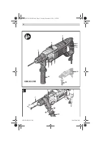
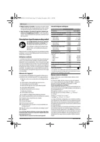
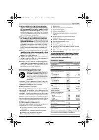
Product Features
The numbering of the product features refers to the illustra-
tion of the machine on the graphics page.
1
Key-type drill chuck with automatic locking feature
2
“Drilling/Impact Drilling” selector switch
3
Rotational direction switch
4
Lock-on button for On/Off switch
5
On/Off switch
6
Thumbwheel for speed preselection
7
Depth stop
8
Gear selector
9
Wing bolt for depth stop adjustment
10
Auxiliary handle (insulated gripping surface)
11
Handle (insulated gripping surface)
12
Chuck key
13
Screwdriver bit *
14
Universal bit holder *
15
Chuck key for key-type drill chuck (manual locking) *
16
Key-type drill chuck (manual locking) *
17
Open-end spanner **
* Accessories shown or described are not part of the standard de-
livery scope of the product. A complete overview of accessories
can be found in our accessories program.
** Commercially available (not included in the delivery scope)
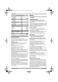
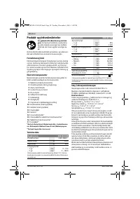
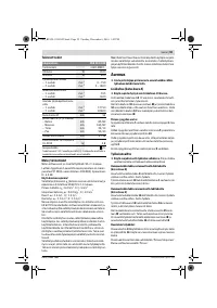
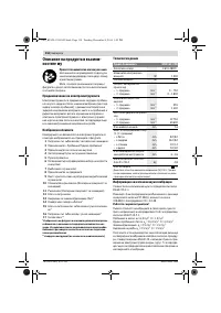
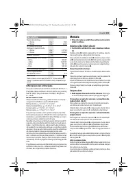
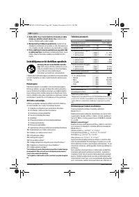
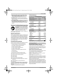
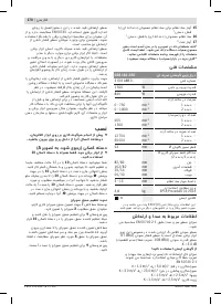
Technical Data
Noise/Vibration Information
Sound emission values determined according to
EN 60745-2-1.
Typically the A-weighted noise levels of the product are:
Sound pressure level 97 dB(A); Sound power level
108 dB(A). Uncertainty K = 3.0 dB.
Wear hearing protection!
Vibration total values a
h
(triax vector sum) and uncertainty K
determined according to EN 60745-2-1:
Drilling into metal: a
h
= 6.0 m/s
2
, K = 1.5 m/s
2
Impact drilling into concrete: a
h
= 23.0 m/s
2
, K = 3.0 m/s
2
Screwdriving without impact: a
h
< 2.5 m/s
2
, K = 1.5 m/s
2
Tapping: a
h
< 2.5 m/s
2
, K = 1.5 m/s
2
The vibration level given in this information sheet has been
measured in accordance with a standardised test given in
EN 60745 and may be used to compare one tool with anoth-
er. It may be used for a preliminary assessment of exposure.
The declared vibration emission level represents the main ap-
plications of the tool. However if the tool is used for different
applications, with different accessories or insertion tools or is
poorly maintained, the vibration emission may differ. This
may significantly increase the exposure level over the total
working period.
An estimation of the level of exposure to vibration should also
take into account the times when the tool is switched off or
when it is running but not actually doing the job. This may sig-
nificantly reduce the exposure level over the total working
period.
Identify additional safety measures to protect the operator
from the effects of vibration such as: maintain the tool and the
accessories, keep the hands warm, organisation of work pat-
terns.
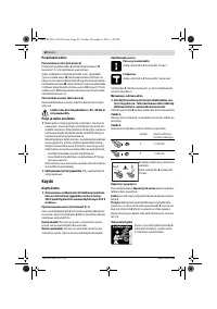
Assembly
Before any work on the machine itself, pull the mains
plug.
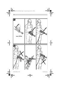
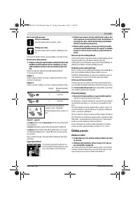
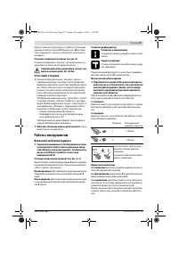
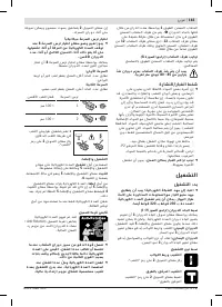
Auxiliary Handle (see figure A)
Operate your machine only with the auxiliary handle
10.
The auxiliary handle
10
can be set in 12 positions to achieve
a safe and low-fatigue working stance.
Turn the bottom part of the auxiliary handle
10
in rotation di-
rection
and push the auxiliary handle
10
forward until you
can pivot it to the desired position. Then pull the auxiliary han-
dle
10
back again and tighten it by turning the bottom part of
the auxiliary handle in rotation direction
.
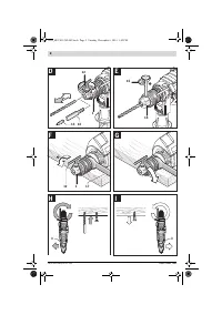
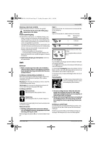
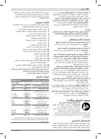
Adjusting the Drilling Depth
The required drilling depth
X
can be set with the depth stop
7
.
Loosen the wing bolt for the depth stop adjustment
9
and in-
sert the depth stop rod into the auxiliary handle
10
.
Pull out the depth stop until the distance between the tip of
the drill bit and the tip of the depth stop corresponds with the
desired drilling depth
X
.
Retighten the wing bolt for the depth stop adjustment
9
again.
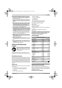
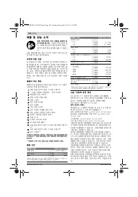
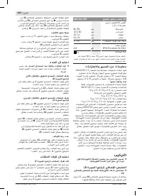
Impact Drill
GSB 162-2 RE
Article number
3 601 A8B 0..
Rated power input
W
1 500
Output power
W
840
No-load speed
– 1st gear
– 2nd gear
min
-1
min
-1
0 – 750
0 – 1 800
Rated speed
– 1st gear
– 2nd gear
min
-1
min
-1
555
1 300
Impact frequency at no-load
– 1st gear
– 2nd gear
min
-1
min
-1
12 750
30 600
Spindle collar dia.
mm
53
Maximum drilling diameter
(1st/2nd gear)
– Concrete
– Brickwork
– Steel
– Wood
mm
mm
mm
mm
82 / 82
162 / 82
20 / 14
50 / 30
Chuck clamping range
mm
3 – 16
Weight according to EPTA-
Procedure 01:2014
kg
4.8
Protection class
/
II
The values given are valid for a nominal voltage [U] of 230 V. For differ-
ent voltages and models for specific countries, these values can vary.
OBJ_BUCH-1294-003.book Page 13 Tuesday, December 6, 2016 1:42 PM
Содержание
- 94 Указания по технике безопасности для дрелей
- 95 Описание продукта и услуг; Применение по назначению
- 96 Данные по шуму и вибрации; Сборка; Замена рабочего инструмента; Смена сверлильного патрона
- 97 Отсос пыли и стружки; Работа с инструментом; Включение электроинструмента
- 98 Указания по применению; Техобслуживание и сервис; Техобслуживание и очистка
- 99 Утилизация; Українська; Вказівки з техніки безпеки; Загальні застереження для електроприладів
Характеристики

Остались вопросы?Не нашли свой ответ в руководстве или возникли другие проблемы? Задайте свой вопрос в форме ниже с подробным описанием вашей ситуации, чтобы другие люди и специалисты смогли дать на него ответ. Если вы знаете как решить проблему другого человека, пожалуйста, подскажите ему :)


