
Дрели Bosch GDB 350 WE - инструкция пользователя по применению, эксплуатации и установке на русском языке. Мы надеемся, она поможет вам решить возникшие у вас вопросы при эксплуатации техники.
Если остались вопросы, задайте их в комментариях после инструкции.
"Загружаем инструкцию", означает, что нужно подождать пока файл загрузится и можно будет его читать онлайн. Некоторые инструкции очень большие и время их появления зависит от вашей скорости интернета.


English |
19
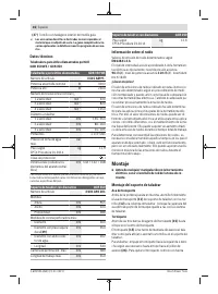
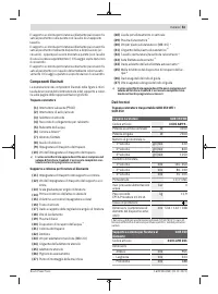
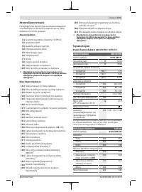
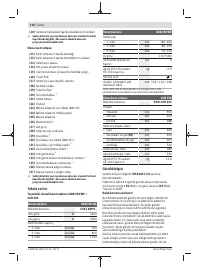
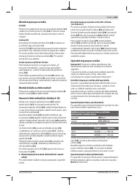
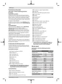
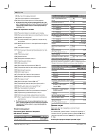
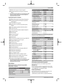
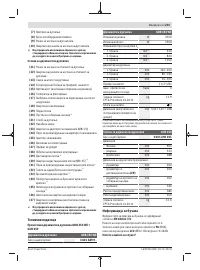
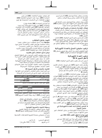
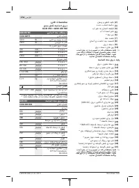
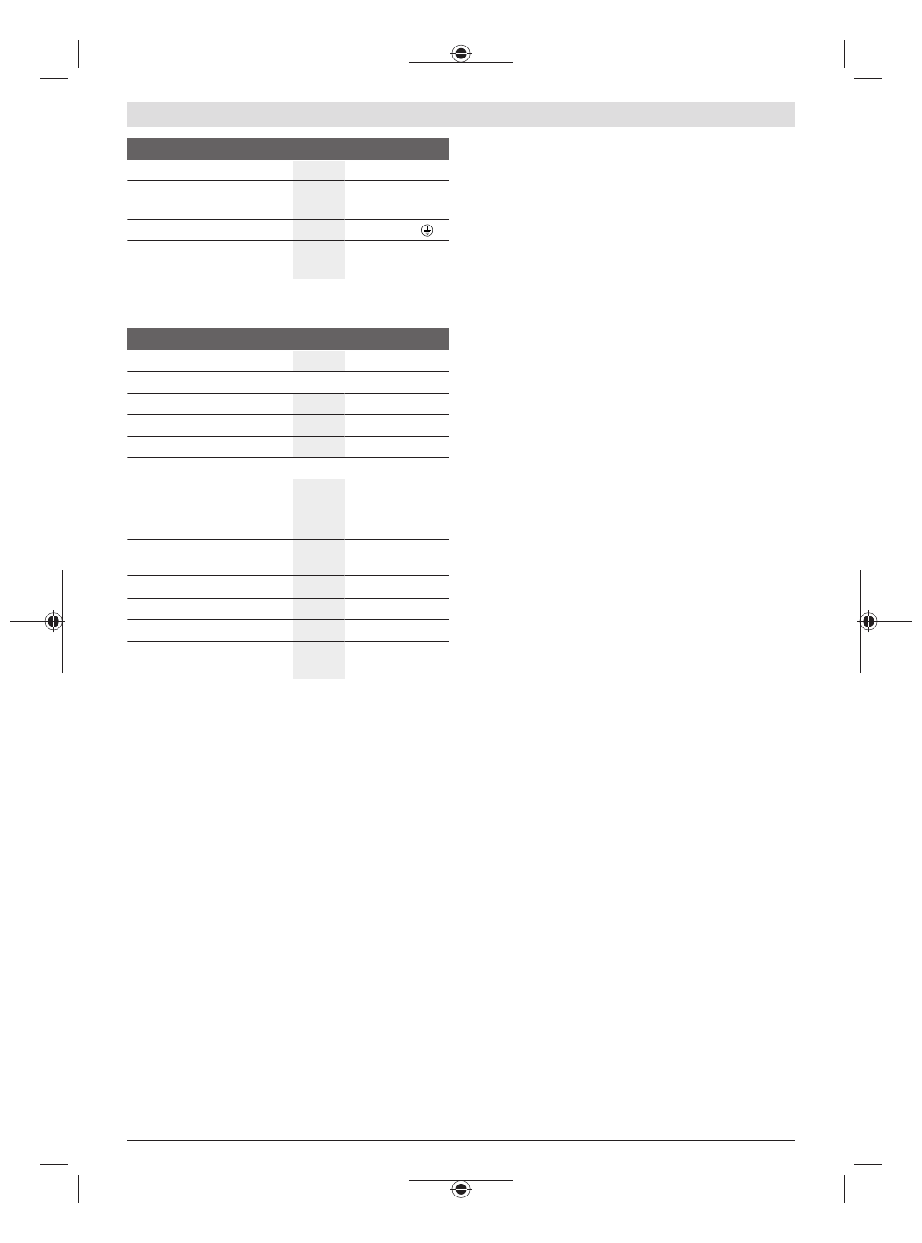
Diamond drill
GDB 350 WE
Max. pressure of water supply
bar
3
Weight according to
EPTA-Procedure 01:2014
kg
11.9
Protection class
/ I
Dimensions (including de-
tachable parts of the tool)
mm 534 × 142 × 168
The specifications apply to a rated voltage [U] of 230 V. These spe-
cifications may vary at different voltages and in country-specific mod-
els.
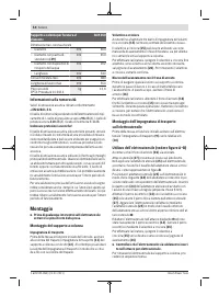
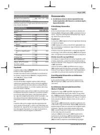
Drill stand for diamond drills
GCR 350
Article number
3 601 A90 201
Dimensions
– Height
mm
955
– Width
mm
323
– Depth
mm
388
Dimensions of core bit, max.
– Diameter
mm
300
– Diameter with spacer
plate
(29)
mm
350
– Diameter with water collec-
tion ring
mm
202
– Length
mm
530
Drill stroke max.
mm
580
Working length max.
mm
550
Weight according to
EPTA-Procedure 01:2014
kg
12.6
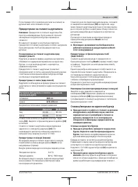
Noise information
Noise emission values determined according to
EN 62841‑3‑6
.
Typically the A-weighted noise level of the power tool is:
Sound pressure level
96
dB(A); sound power level
110
dB(A). Uncertainty K=
3
dB.
Wear hearing protection
The noise emission value given in these instructions has
been measured in accordance with a standardised measur-
ing procedure and may be used to compare power tools. It
may also be used for a preliminary estimation of noise emis-
sions.
The noise emission value given represents the main applica-
tions of the power tool. However, if the power tool is used
for other applications, with different application tools or is
poorly maintained, the noise emission value may differ. This
may significantly increase noise emissions over the total
working period.
To estimate noise emissions accurately, the times when the
tool is switched off, or when it is running but not actually be-
ing used, should also be taken into account. This may signi-
ficantly reduce noise emissions over the total working
period.
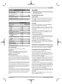
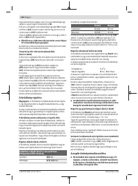
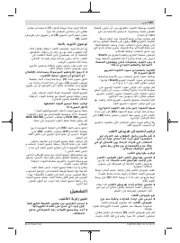
Assembly
u
Pull the plug out of the socket before carrying out any
work on the power tool.
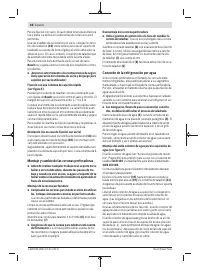
Assembling the drill stand
Carrying handle
Before initial commissioning, screw the drill stand carrying
handle
(11)
firmly in place on the drill column using the
screws
(12)
. In doing so, position the cap of the carrying
handle so that it closes in line with the drill column.
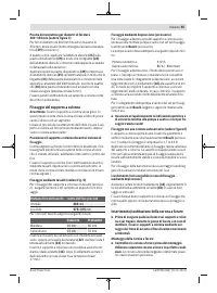
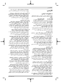
Star handle
Screw the three handlebars of the star handle
(15)
all the
way into the central hub of the star handle.
The star handle
(15)
serves both as the feed crank during
drilling and as a means of loosening or tightening screws on
the drill stand.
To drill, push the star handle all the way to the left or right
(as required) and onto the feed pinion
(26)
. Pull the star
handle off firmly to remove it.
Feed lock with locking brake
Lock the feed when performing any work on the drill stand,
during breaks and when not using the drill stand. Do this by
engaging the locking brake
(16)
.
To drill, loosen the locking brake
(16)
until the star
handle
(15)
is easy to move. When doing so, hold the star
handle in place to prevent the power tool from sliding down
in an uncontrolled manner.
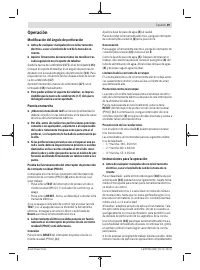
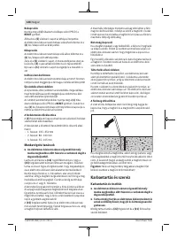
Attaching the carrying handle to the power tool
Before initial commissioning, screw the carrying handle
(9)
firmly in place on the power tool using the screws
(10)
.
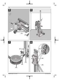
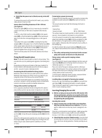
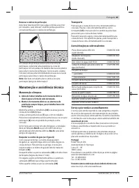
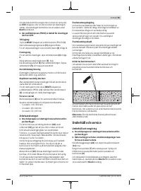
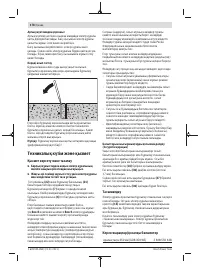
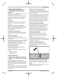
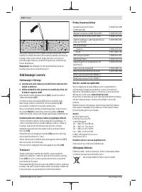
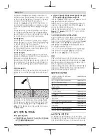
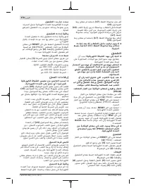
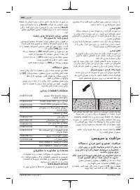
Inserting the power tool (see figures A–B)
Ensure that the locking brake
(16)
is on.
The drill holder
(27)
has a recess on the right-hand side.
When placing the machine adapter
(25)
onto the power tool,
ensure that the flange on the machine adapter also sits on
the right as shown in the diagram
B
.
Position the machine adapter
(25)
on the power tool so that
the feather keys
(24)
of the machine adapter click into the
corresponding recesses of the power tool. Insert the four
screws
(23)
of the machine adapter and tighten them using
a hex key (size 6 mm).
Loosen the eccentric bolt
(14)
using the star handle
(15)
and pull it as far as possible out of the drill holder
(27)
. Use
the machine adapter
(25)
to hang the power tool in the drill
holder so that the lower lip of the machine adapter sits be-
hind the lower bolt of the drill holder
➊
.
Hinge the power tool into the drill holder
➋
and reinsert the
eccentric bolt
(14)
. Tighten the eccentric bolt using the star
handle
(15)
.
Slide the star handle
(15)
to the right or left and onto the
feed pinion
(26)
in order to drill.
Bosch Power Tools
1 609 92A 4NK | (21.01.2021)
Характеристики

Остались вопросы?Не нашли свой ответ в руководстве или возникли другие проблемы? Задайте свой вопрос в форме ниже с подробным описанием вашей ситуации, чтобы другие люди и специалисты смогли дать на него ответ. Если вы знаете как решить проблему другого человека, пожалуйста, подскажите ему :)


