
Вытяжки Smeg KDV907X - инструкция пользователя по применению, эксплуатации и установке на русском языке. Мы надеемся, она поможет вам решить возникшие у вас вопросы при эксплуатации техники.
Если остались вопросы, задайте их в комментариях после инструкции.
"Загружаем инструкцию", означает, что нужно подождать пока файл загрузится и можно будет его читать онлайн. Некоторые инструкции очень большие и время их появления зависит от вашей скорости интернета.


19
connect a fumes discharge device to the outside (only
suction version).
• Carry out all the masonry work necessary (e.g.
installation of an electric socket and/or a hole for the
passage of the discharge tube).
Expansion wall plugs are provided to secure the hood to most
types of walls/ceilings. However, a qualified technician must
verify suitability of the materials in accordance with the type of
wall/ceiling. The wall/ceiling must be strong enough to take
the weight of the hood.
Do not tile, grout or silicone this
appliance to the wall. Surface mounting only.
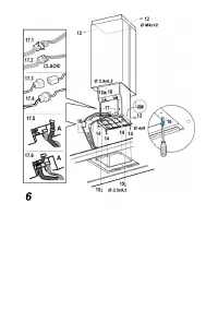
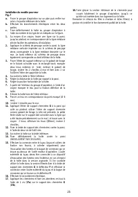
Installation ceiling model (Island)
Fig. 5-6
1.
Adjust extension of the hood support structure, as the
final height of the hood depends on this.
Note:
In some cases the upper section of the lattice is
fixed to the lower section with one or more screws,
eventually check and remove them temporarily to allow
the adjustment of the support structure.
2.
Fix the two sections of the structure with a total of 16
screws (four per corner).
Apply one or two brackets to the upper section for
extensions greater than the minimum (on the basis of
that envisaged supplied) to reinforce it.
Note:
For transport reasons 1 bracket may already be
fixed to the trellis with 2 screws in a temporary manner, it
is therefore possible to either shift it to the required
position, or definitively secure its fixture with 6 additional
screws.
Proceed as follows for this purpose:
a.
Slightly widen the fixing brackets so that they can be
applied to the exterior of the structure.
b.
Position the reinforcement bracket immediately above
the fixing point of the two sections of the structure and fix
with a total of 8 screws (2 per corner).
If supplied, fix the second reinforcement bracket in a
position equidistant between the first reinforcement
bracket and the upper side of the lattice, fix with 8 screws
(2 per corner).
Note:
in positioning and fixing the reinforcement
bracket/s check that these do not prevent fixing the
discharge tube (suction version) or the baffle (filtering
version) easily.
3.
Apply the perforation diagram vertically over the cooking
top to the ceiling (the centre of the diagram should
correspond to the centre of the cooking top and the sides
should be parallel to the sides of the cooking top – the
side of the diagram with the word FRONT corresponds to
the control panel). Make the electrical connection.
4.
Drill as shown (6 holes for 6 wall plugs – 4 plugs for
fixture), screw the outer screws leaving a space of about
1 cm. between the screw head and the ceiling.
5.
Put a discharge tube inside the lattice and connect it to
the joining ring of the motor compartment (discharge tube
and fixing clamp not supplied). The discharge tube must
be sufficiently long to reach the outside (suction version)
or deflector F (Filter version).
6. Only for the filter version: mount deflector F
onto the
lattice and fix it with 4 screws to the apposite bracket.
Finally, connect the discharge tube to the connecting ring
on the deflector.
7.
Apply two nuts to the right and left sides of the lattice
(upper part) in the square slots. They will serve to tighten
the fixing screws of the upper flue.
8.
Attach the lattice to the ceiling with the 4 screws (see
operation 4).
9.
Screw the 4 screws up decisively.
10.
Put 2 more screws in the holes for fixing the safety
elements remaining free and screw them up decisively.
11.
Connect the electricity to the mains. The mains must be
turned on only after installation has been concluded.
12.
Put the upper flue (the one with the slots) onto the lattice
and fix it to the lattice near the ceiling with 2 screws (one
per side). Then put the lower flue onto the lattice and fix
the lower flue to the upper flue temporarily with 1 screw.
Check the hold of the two flues.
Note:
In order to permit the temporary fixture it will be
necessary to insert the lower shaft to cover the top one,
right to the end of the run,
overtaking the screw that fixes the upper shaft to the
bracket in the vicinity of the ceiling.
13.
Put 2 clips onto the sides of the fixing points between the
lattice and the hood.
14.
Attach the hood to the lattice. Check the perfect
attachment - screw 4 screws partially up to attach the
hood to the lattice.
ATTENTION!
The side of the lattice with the connection
box corresponds to the side of the control panel once the
hood is mounted.
15.
Fix the hood to the lattice with two screws. They will also
serve to center the two parts.
16.
Screw the 4 screws that fix the lattice to the hood up
decisively.
17.
Carry out the electrical connection of the command
instrument board and the lamps.
18.
Holding the lower flue carefully, remove the temporary
fixing screws between the upper and lower flues (see
installation phase 12) and bring the lower flue flush over
the hood (put the flue into its seat).
19.
Turn the mains on again, acting on the central electrical
panel and check the correct functioning of the hood.
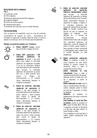
Choose the cooking top and calibration of the sensors (to do
this read the functioning instructions of the control panel
carefully).
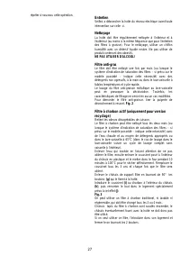
Installation wall model
Fig. 7
a.
Rest the suction unit on a flat surface and thread the
lower part of the hood onto it.
b.
Make all the electrical connections between the two
parts.
c.
Fix the hood definitively to the suction unit with the
number and type of screws indicated in the figure.
1.
Using a pencil, draw a line on the wall, extending up to
the ceiling, to mark the centre. This will facilitate
installation.
2.
Rest the drilling template against the wall: the vertical
Характеристики

Остались вопросы?Не нашли свой ответ в руководстве или возникли другие проблемы? Задайте свой вопрос в форме ниже с подробным описанием вашей ситуации, чтобы другие люди и специалисты смогли дать на него ответ. Если вы знаете как решить проблему другого человека, пожалуйста, подскажите ему :)


