
Вытяжки Falmec Luce 90 Glass island - инструкция пользователя по применению, эксплуатации и установке на русском языке. Мы надеемся, она поможет вам решить возникшие у вас вопросы при эксплуатации техники.
Если остались вопросы, задайте их в комментариях после инструкции.
"Загружаем инструкцию", означает, что нужно подождать пока файл загрузится и можно будет его читать онлайн. Некоторые инструкции очень большие и время их появления зависит от вашей скорости интернета.


21
eNgLish
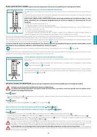
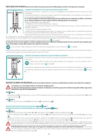
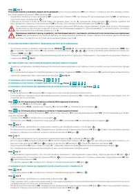
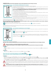
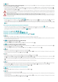
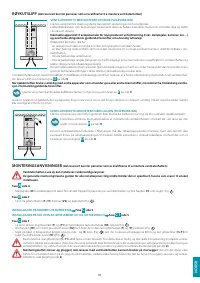
fumes DischArge
(only intended for personnel qualiied to assemble the hood)
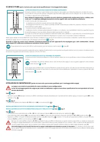
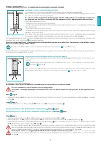
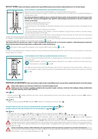
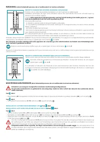
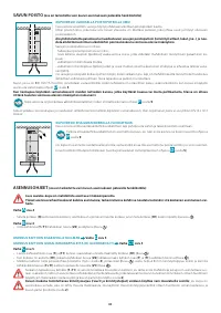
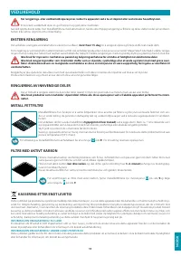
eXterNAL eXhAust hooD versioN (suctioN)
In this version, the kitchen fumes and vapours are conveyed outside through an exhaust pipe.
The air outlet itting that extends from the upper part of the hood must be connected with the pipe that conducts
the fumes and vapours to an external output.
Do not connect the equipment to discharge pipes of fumes produced from combustion (for example boil-
ers, ireplaces, etc) and you are to comply with the regulations in force regarding external air discharge.
The fumes outlet pipe must have:
- a diameter not less than that of the hood itting;
- a slight slope downwards (drop) in the horizontal sections to prevent any formation of condensation from lowing
back to the hood;
- the minimum required number of bends;
- minimum required length (long pipes with various bends can reduce suction performance of the hood and trigger
vibrations of the check valve).
If the fumes outlet pipe passes through cold environments such as attics, etc., it is possible that water condensation
forms due to sudden changes in temperature. In this case, you are required to insulate the pipes.
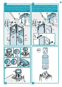
The hood supplied with an 800 m
3
/h motor is equipped with a check valve whose function is to prevent external air exchange when the hood is not
operating: refer to the instructions
D
on page
5
for assembly.
When the kitchen hood is used simultaneously with other appliances that use gas or other fuels, the room must have suicient ventila-
tion, in accordance with regulations in force.
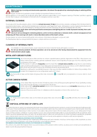
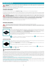
The active carbon ilters in this version are to be removed. Refer to the instructions
P
on page
9
for removal.
Deviation for Germany: when the kitchen hood is used at the same time as appliances that are powered by energy other than electricity, the negative pressure
in the room must not exceed 4 Pa (4 x 10⁻⁵ bar).
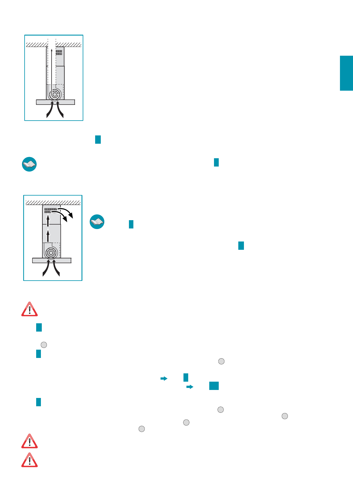
hooD versioN With iNterNAL recircuLAtioN (fiLteriNg)
In this model, air passes through the active carbon ilters to be puriied and is then recycled into the kitchen envi-
ronment.
Check that the active carbon ilters are assembled onto the hood, if not, install them as indicated in the in-
structions
P
on page
9
.
If the hood is set up with a iltering version, the check valve must not be assembled: remove it if it is on the air outlet
itting of the motor (carry out operations described in the instructions
D
on page
5
in reverse order).
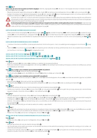
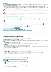
AssemBLY iNstructioNs
(only intended for personnel qualiied to assemble the hood)
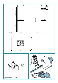
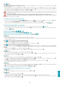
the Luce island hood can be installed in various conigurations.
the generic assembly steps apply to all installations; for each case, follow the speciic steps provided for the required installa-
tion.
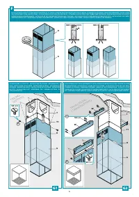
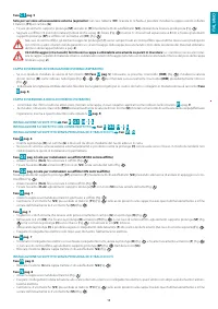
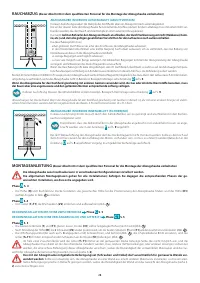
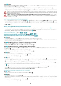
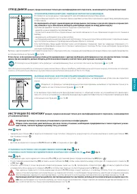
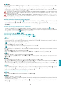
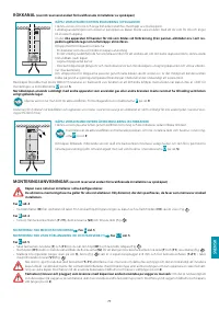
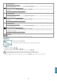
Phase
D
page 4
•
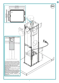
Measure the distance (
h
) from cooker to ceiling; decide the height you wish to position the hood at and take the measurement (
h1
) as illustrated
in Fig.
1
.
Phase
B
page 4
•
Take the trellis down from the assembly (
t
+
t1
) the 8 screws (
v2
) and put them aside (Fig.
1
).
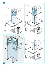
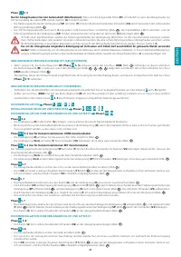
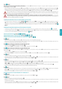
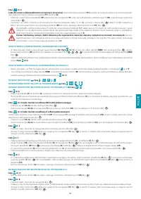
iNstALLAtioN oN ceiLiNg With/Without fALse ceiLiNg
Phase
c
page 5
iNstALLAtioN oN ceiLiNg Without eXteNsioN (h) AND treLLis (t)
Phase
c1
page 5
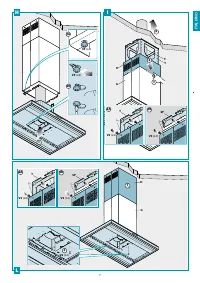
Phase
c
page 5
•
Slide the two parts of the trellis (
t
) and (
t1
) to the previously established height (
h1
) (Fig.
1
).
•
When the height is set (
h1
), put the 8 screws back in (
v2
) to secure the two parts of the trellis (
t
) and (
t1
) together (Fig.
2
).
•
Mark 4 drilling points on the ceiling (also identiied on page
3
), drill (Fig.
3
) Put in 4 x ø 8mm expansion bolts and secure the trellis assembly
(
t+t1
) to the ceiling by the relative screws (
v1
) (Fig.
4
).
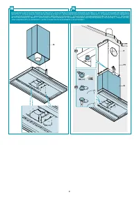
With false ceilings, the trellis (
t
+
t1
) must always be bolted to a masonry ceiling: if this is not possible and it is necessary to attach the hood
directly to the false ceiling, said false ceiling must be reinforced or somehow itted with a solution that can guarantee safely attaching the
hood to it, taking into account the strength of the used materials and the weight of the hood (reported on page
2
).
the ixing kit (screws and plugs) supplied with the hood can only be used on masonry walls:
should it be necessary to install the
hood onto walls in a diferent material, assess other ixing systems keeping the wall resistance and weight of the hood in mind (indicated
on page
2
).
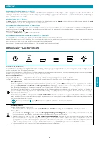
Содержание
- 47 СиЙ; ТехНиКА; МерЫ ПреДОСТОрОжНОСТи ДЛя УСТАНОВщиКА; МерЫ ПреДОСТОрОжНОСТи ДЛя ПОЛьзОВАТеЛя
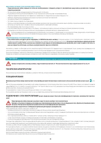
- 48 УСТАНОВКА; ТехНичеСКие хАрАКТериСТиКи
- 49 иНСТрУКции ПО МОНТАжУ
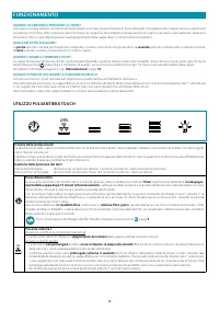
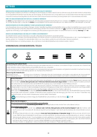
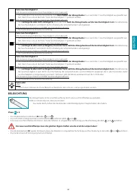
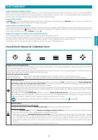
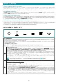
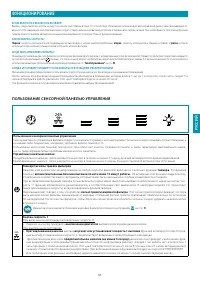
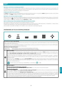
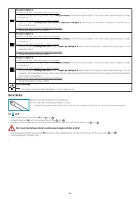
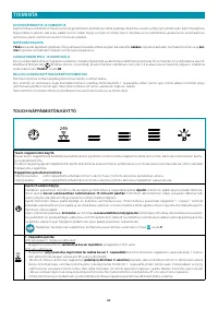
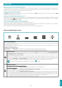
- 51 фУНКциОНирОВАНие; ПОЛьзОВАНие СеНСОрНОЙ ПАНеЛьЮ УПрАВЛеНия
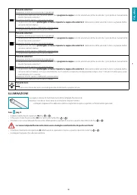
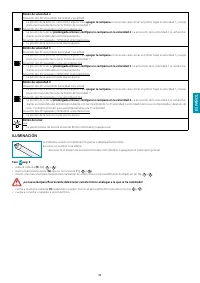
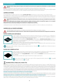
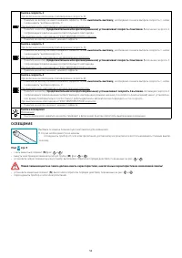
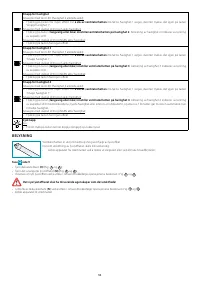
- 52 ОСВещеНие
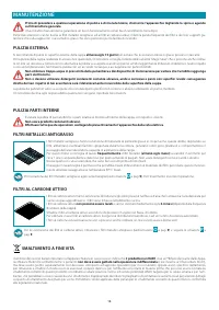
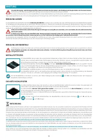
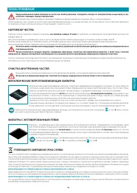
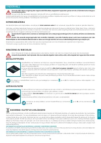
- 53 Тех; НАрУжНАя чиСТКА; фиЛьТрЫ С АКТиВирОВАННЫМ УгЛеМ; УТиЛизАция ПО зАВершеНии СрОКА СЛУжБЫ
Характеристики

Остались вопросы?Не нашли свой ответ в руководстве или возникли другие проблемы? Задайте свой вопрос в форме ниже с подробным описанием вашей ситуации, чтобы другие люди и специалисты смогли дать на него ответ. Если вы знаете как решить проблему другого человека, пожалуйста, подскажите ему :)


