Водонагреватели Tesy GCV 2005624 - инструкция пользователя по применению, эксплуатации и установке на русском языке. Мы надеемся, она поможет вам решить возникшие у вас вопросы при эксплуатации техники.
Если остались вопросы, задайте их в комментариях после инструкции.
"Загружаем инструкцию", означает, что нужно подождать пока файл загрузится и можно будет его читать онлайн. Некоторые инструкции очень большие и время их появления зависит от вашей скорости интернета.


6
EN
IV.
DESCRIPTION AND PRINCIPLE OF WORK
The appliance consists of a boiler shell, a flange at its lower end /with
vertically-installed boilers/ or lateral flange/with horizontally-installed
boilers/, protective plastic panel and non-return safety valve.
1.
The body consists of a steel reservoir (water tank) and housing (outer
shell) with thermal insulation placed in-between made of ecologically clean
high density polyurethane foam, and two pipes with thread G (table 1 to
fig. 1a; table 2 to fig. 1b) for cold water supply (marked by a blue ring) and
hot water outlet pipe (marked by a red ring).
The inner tank may be of two types depending on the model:
•
Made of steel protected form corrosion by a special glass-ceramics
coating
•
Made of stainless steel
The vertical water heaters may be outfitted with a built in heat exchange
unit (boiler tube). The boiler tube’s entrance and exit are located at the
sides and represent pipes with thread G ¾ “.
2.
The flange is outfitted with: electric heater and thermostat. The water
heaters with glass-ceramics coating are outfitted with a magnesium
protector.
The electric heater is used for heating the water in the tank and is
managed by the thermostat, which automatically maintains the set
temperature.
The thermostat has a built in overheating safety device, which switches
of power to the heater when the water temperature reaches excessive
values.
3.
The safety-return valve prevents the appliance’s complete emptying
in the event the cold water supply is interrupted. The valve protects the
appliance from pressure increases higher than the allowed value during
heating (! pressure increases upon an increase of temperature), via
release of excess pressure during the drainage opening
Attention! The safety-return valve cannot protect the appliance in the
event of water mains pressure in excess of the acceptable pressure
stated for the appliance.
V.
MOUNTING AND SWITCHING ON
Attention! Improper installation and connection of the appliance may
make it hazardous for the health and life of consumers. It may cause
grievous and permanent consequences, including but not limited to physical
injuries and/or death. Improper installation and connection of the appliance
may also lead to damage to the consumers’ property /damage and/ or
destruction/, or to that of third persons, as a result of, but not limited to
flooding, explosion and/or fire.
Installation, connection to the main water and power supply, and putting
into operation must be carried out by certified electricians and technical
personnel certified in installation of this category of appliances, who have
obtained their license in the state where the installation and commissioning
of the appliance are carried out, and in compliance with its local legislation.
1.
Mounting
We recommend the mounting of the device at close proximity to locations where hot
water is used, in order to reduce heat losses during transportation. In the event the
device is mounted in a bathroom, the selected location must exclude the possibility
of water spray contact from the showerhead or portable showerhead attachment.
Two methods of installation are possible:
•
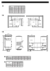
Vertical installation (fig. 1a, table 1) – When installing the appliance onto a wall
– the boiler should be hanged through the upper carrying plate which is fixed to the
appliance shell.
Two hooks are used for suspending the appliance (min. Ø 10 mm) set firmly in
the wall (not included in the mounting set). The mounting bracket’s construction
designed for water heaters intended for vertical mounting is universal and allows a
distance between the hooks of 220 to 310 mm - fig.1a.
•
Vertical installation (fig. 1b, table 2)
When installing the water heaters models with a diameter of 560 mm follow the
installation instructions in fig. 1b.
It is obligatory that the appliance is hanged through the two carrying plates which are
fixed to its shell.
Attention! It is forbidden to install the appliance (models with a
diameter of 560 mm) with hooks.
•
Horizontal installation GCVH and GCH models (fig.1c, 1d) – At
horizontal installation the distances between the carrying hooks are different
with the different capacities and these values are indicated in table 3 - fig.1c
and table 4 - fig. 1d.
Warning! The appliance must be installed in such a way, so as the
protective plastic panel and the inlet/outlet pipes to remain on the left
side of the boiler (frontal view). The cold water supply pipe (with a blue ring)
must be beneath the hot water discharge pipe (with a red ring).
Attention! In order to prevent injury to user and third persons in the
event of faults in the system for providing hot water, the appliance
must be mounted in premises outfitted with floor hydro insulation and
plumbing drainage. Don’t place objects, which are not waterproof under the
appliance under any circumstances. In the event of mounting the appliance
in premises not outfitted with floor hydro insulation, a protective tub with a
plumbing drainage must be placed under the appliance.
Notice
: the set does not include a protective tub and the user must
select the same.
2.
Water heater connection to the pipe network
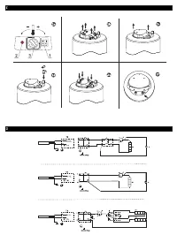
Fig. 4: a) - for vertical installation; b) - for horizontal installation GCVH; c) -
for horizontal installation GCH;
Where: 1 - Inlet pipe; 2 - Safety valve; 3 - reducing valve (for water main
pressure > 0,6 MPa); 4 - Stop valve; 5 - Funnel connected to the sewer
network; 6 – Hose; 7 - Drain water tap.
Upon connecting the water heater to the water mains you must consider
the indicative color markings /rings/ affixed to the pipes: blue for cold /
incoming/ water, red for hot /outgoing/ water.
The mounting of the safety return-valve supplied with the water
heater is obligatory.
The safety return-valve must be mounted on the
cold water supply pipe, in observance of the direction arrow stamped on
its body, indicating the incoming water’s direction. Additional stopcocks
must not be mounted between the safety return-valve and the water
heater.
Exception: If the local regulations (norms) require the usage of another
protection valve or mechanism (in accordance with EN 1487 or EN
1489), then it must be bought additionally. For mechanisms operating in
accordance with EN 1487 the announced operational pressure must be
no more than 0.7 MPa. For other protection valves, the pressure at which
they are calibrated must be 0.1 MPa lower than the one marked on the
appliance’s sign. In these cases the safety valve which the appliance is
supplied with should not be used.
Attention! The presence of other /old/ safety return-valves may lead to
a breakdown of your appliance and they must be removed.
Attention! Other type of stopping armature is not allowed between the
protection return valve (the protective device) and the appliance.
Attention! The attaching of the safety return-valve to pipes with
threads G ½ ‘’ longer than 10 mm is not allowed, otherwise this may
damage the valve and poses danger for your appliance.
Attention! With boilers for vertical assembly, the safety valve has to be
connected to the ingoing pipe with the safety plastic panel of the
appliance being taken off. After it has been assembled it should be in
position as shown on Fig. 2.
Attention! The safety valve and the pipe between the valve and the
water heater must be protected from freezing. During hose draining -
its free end must be always open to the atmosphere (not to be immersed).
Make sure that the hose is also protected from freezing.
Opening the cold-water stopcock of the water supply piping network and
opening the hot-water stopcock of the water-mixing faucet carries out the
filling of the water heater with water. After the filling is complete, a constant
stream of water must begin to flow from the water-mixing faucet. Now you
can close the hot water stopcock.
In the event you must empty the water heater, first you must cut off its
power supply. The inflow of water from the water mains must first be
terminated and the hot water tap of the mixing-faucet must be opened.
The water tap 7 (fig 4a and 4 b) must be opened to drain the water from
water tank. If there is no such tap build in the pipe line, than the water can
be drain as follow:
•
Models equipped with safety valve with lever - You can drain the water
from the water heater by lifting the safety return-valve’s lever. Water will
drain from the safety return-valve’s drainage opening
•
Models equipped with safety valve without lever - water can be drain
directly from inlet pipe of water tank after when you disconnect it from
water main
In the event of removing the flange, the discharge of several liters of
water, which remain in the water tank, is normal.
Attention! Measures must be undertaken to prevent damage from
discharging water during draining.
In case that the pressure in the water mains is over the value pointed out
in the above paragraph I, then it is necessary to assemble a pressure
reduce valve, otherwise the water heater would not function properly. The
Manufacturer does not assume any liability for problems arising out of the
appliance’s improper use.
3.
Water heater connection to the electrical network.
Attention! Make sure the appliance is full of water prior to switching on
the electrical mains power.
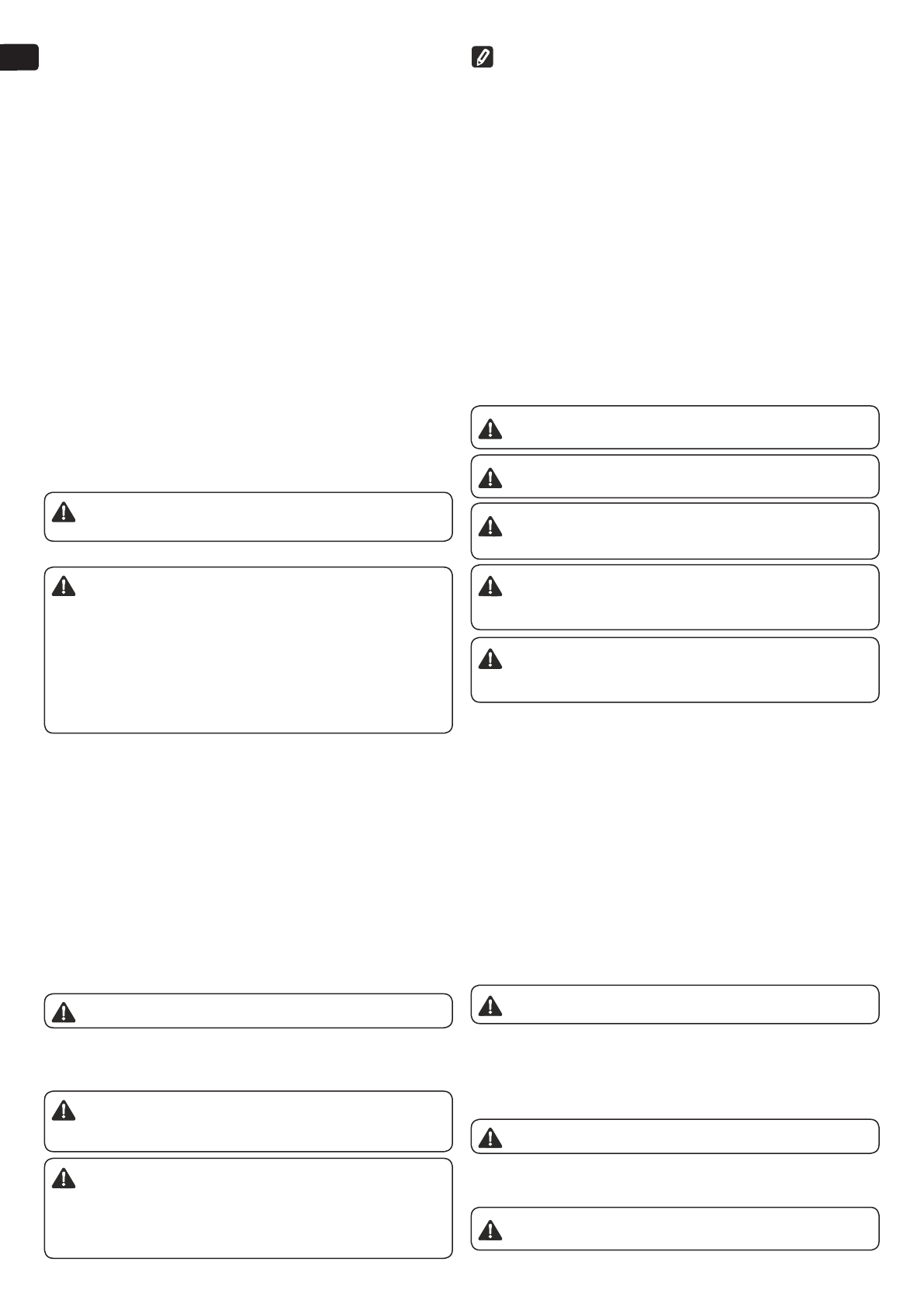
3.1.
Models with power cord with a plug are connected by inserting the
plug into a contact. They are switched off the power supply by drawing the
plug out of the contact.
Attention! The wall-plug must be properly connected to a separate
electrical circle that is provided with a protector. It must be earthed.
Характеристики

Остались вопросы?Не нашли свой ответ в руководстве или возникли другие проблемы? Задайте свой вопрос в форме ниже с подробным описанием вашей ситуации, чтобы другие люди и специалисты смогли дать на него ответ. Если вы знаете как решить проблему другого человека, пожалуйста, подскажите ему :)
