
Водонагреватели TESY GCV 1004724D C22 ECW - инструкция пользователя по применению, эксплуатации и установке на русском языке. Мы надеемся, она поможет вам решить возникшие у вас вопросы при эксплуатации техники.
Если остались вопросы, задайте их в комментариях после инструкции.
"Загружаем инструкцию", означает, что нужно подождать пока файл загрузится и можно будет его читать онлайн. Некоторые инструкции очень большие и время их появления зависит от вашей скорости интернета.
8
Instructions for use and maintenance
EN
1.
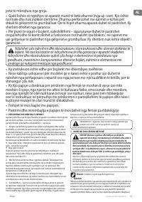
Mounting
We recommend the mounting of the device at close proximity to
locations where hot water is used, in order to reduce heat losses during
transportation. In the event the device is mounted in a bathroom, the
selected location must exclude the possibility of water spray contact
from the showerhead or portable showerhead attachment.
The appliance is affixed to a wall via the mounting brackets attached to
the unit’s body (if the brackets are not attached to the unit’s body, they
must be affixed in place via the provided bolts). Two hooks are used
for suspending the appliance (min. Ø 10 mm) set firmly in the wall (not
included in the mounting set). The mounting bracket’s construction
designed for water heaters intended for vertical mounting is universal
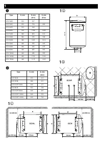
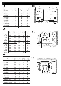
and allows a distance between the hooks of 220 to 310 mm (fig. 1a). For
water heaters intended for horizontal mounting, the distances between
the hooks vary for the different models and are specified in the table
2 to Fig. 1c. For water heaters intended for floor installation - table 2
to Fig. 1b.
In order to prevent injury to user and third persons in the
event of faults in the system for providing hot water, the
appliance must be mounted in premises outfitted with floor hydro
insulation and plumbing drainage. Don’t place objects, which are
not waterproof under the appliance under any circumstances. In
the event of mounting the appliance in premises not outfitted
with floor hydro insulation, a protective tub with a plumbing
drainage must be placed under the appliance.
Notice
: the set does not include a protective tub and the user must
select the same.
2.
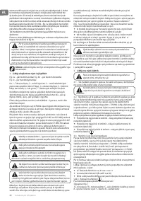
Water heater connection to the pipe network.
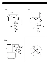
Fig. 3: a) - for vertical; b) - for horizontal installation; c) - for floor
installation
Where: 1 - Inlet pipe; 2 - Safety valve; 3 - reducing valve (for water main
pressure > 0,6 MPa); 4 - Stop valve; 5 - Funnel connected to the sewer
network; 6 – Hose; 7 - Drain water tap.
Upon connecting the water heater to the water mains you must consider
the indicative color markings /rings/ affixed to the pipes: blue for cold /
incoming/ water, red for hot /outgoing/ water.
The mounting of the safety return-valve supplied with the water heater
is obligatory. The safety return-valve must be mounted on the cold water
supply pipe, in observance of the direction arrow stamped on its body,
indicating the incoming water’s direction. Additional stopcocks must not
be mounted between the safety return-valve and the water heater.
Exception: If the local regulations (norms) require the usage of another
protection valve or mechanism (in accordance with EN 1487 or EN
1489), then it must be bought additionally. For mechanisms operating in
accordance with EN 1487 the announced operational pressure must be
no more than 0.7 MPa. For other protection valves, the pressure at which
they are calibrated must be 0.1 MPa lower than the one marked on the
appliance’s sign. In these cases the safety valve which the appliance is
supplied with should not be used.
The presence of other /old/ safety return-valves may lead to a
breakdown of your appliance and they must be removed.
Other type of stopping armature is not allowed between the
protection return valve (the protective device) and the appliance.
The attaching of the safety return-valve to threads longer than
10 mm is not allowed, otherwise this may damage the valve
and poses danger for your appliance.
With appliances for vertical assembly, the safety valve has to
be connected to the ingoing pipe with the safety plastic panel
of the appliance being taken off.
The safety valve and the pipe between the valve and the water
heater must be protected from freezing. During hose draining
- its free end must be always open to the atmosphere (not to be
immersed). Make sure that the hose is also protected from freezing.
Opening the cold-water stopcock of the water supply piping network
and opening the hot-water stopcock of the water-mixing faucet
carries out the filling of the water heater with water. After the filling
is complete, a constant stream of water must begin to flow from the
water-mixing faucet. Now you can close the hot water stopcock.
In the event you must empty the water heater, first you must cut off
its power supply. The inflow of water from the water mains must first
be terminated and the hot water tap of the mixing-faucet must be
opened. The water tap 7 (fig 3a and 3b) must be opened to drain the
water from water tank. If there is no such tap build in the pipe line, than
the water can be drain as follow:
•
Models equipped with safety valve with lever - You can drain the
water from the water heater by lifting the safety return-valve’s lever.
Water will drain from the safety return-valve’s drainage opening
•
Models equipped with safety valve without lever - water can be
drain directly from inlet pipe of water tank after when you disconnect
it from water main
In the event of removing the flange, the discharge of several liters of
water, which remain in the water tank, is normal.
Measures must be undertaken to prevent damage from
discharging water during draining.
In case that the pressure in the water mains is over the value
pointed out in the above paragraph I, then it is necessary to
assemble a pressure reduce valve, otherwise the water heater
would not function properly. The Manufacturer does not assume
any liability for problems arising out of the appliance’s improper
use.
3.
Water heater connection to the electrical network
Make sure the appliance is full of water prior to switching on
the electrical mains power.
3.1.
Models with power cord with a plug are connected by
inserting the plug into a contact. They are switched off the power
supply by drawing the plug out of the contact.
The wall-plug must be properly connected to a separate electrical
circle that is provided with a protector. It must be earthed.
3.2.
The appliance has to be connected to a separate electricity
circuit of the stationary electrical wiring. The connecting has to be
constant- with no plug contacts. The circuit has to be supplied with
a safety fuse (16A) and with inbuilt device to ensure disconnection
of all pole pieces in the conditions of over-voltage from category III.
The connecting of the conductors of the supply cord of the
appliance has to be carried out as follows:
•
conductor with brown insulation – to the phase conductor of
the electrical wiring (L)
•
conductor with blue insulation- to the neutral conductor of the
wiring (N)
•
conductor with yellow-green insulation – to the safety
conductor of the wiring (
)
3.3.
Models without power cord
The appliance has to be connected to a separate electricity circuit of
the stationary electrical wiring. The circuit has to be supplied with a
safety fuse 16A (20A for power > 3700W). Copper single core (rigid
– non stranded) conductor shall be used for the connection – cable
3 x 2.5 mm² (cable 3 x 2.5 mm² for power > 3700W).
The electrical circuit supplying the appliance must have an in-built
device ensuring the splitting of all terminal poles under conditions
of super-voltage of category III.
To install the power supply wire to the appliances remove the
plastic cover.
Connect the power wires in compliance with the marks on the
terminals, as follows:
•
the phase - to mark A, A1, L or L1;
•
the neutral - to N (B or B1 or N1)
•
The safety wire must be obligatory connected to the screw joint
marked with
.
After the installation, put the plastic cover back in its place!
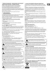
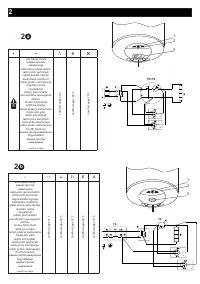
Explanations to Fig. 2:
TS - thermal switch; TR - thermal regulator; S - switch (for models that
have one); R - heater; IL - light indicator; F - flange; KL - luster terminal;
Характеристики

Остались вопросы?Не нашли свой ответ в руководстве или возникли другие проблемы? Задайте свой вопрос в форме ниже с подробным описанием вашей ситуации, чтобы другие люди и специалисты смогли дать на него ответ. Если вы знаете как решить проблему другого человека, пожалуйста, подскажите ему :)
