Вентиляторы Ardesto FN-1608CW - инструкция пользователя по применению, эксплуатации и установке на русском языке. Мы надеемся, она поможет вам решить возникшие у вас вопросы при эксплуатации техники.
Если остались вопросы, задайте их в комментариях после инструкции.
"Загружаем инструкцию", означает, что нужно подождать пока файл загрузится и можно будет его читать онлайн. Некоторые инструкции очень большие и время их появления зависит от вашей скорости интернета.


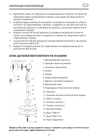


INSTRUCTION MANUAL
EN
16
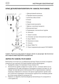
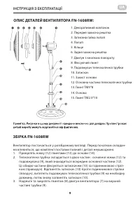
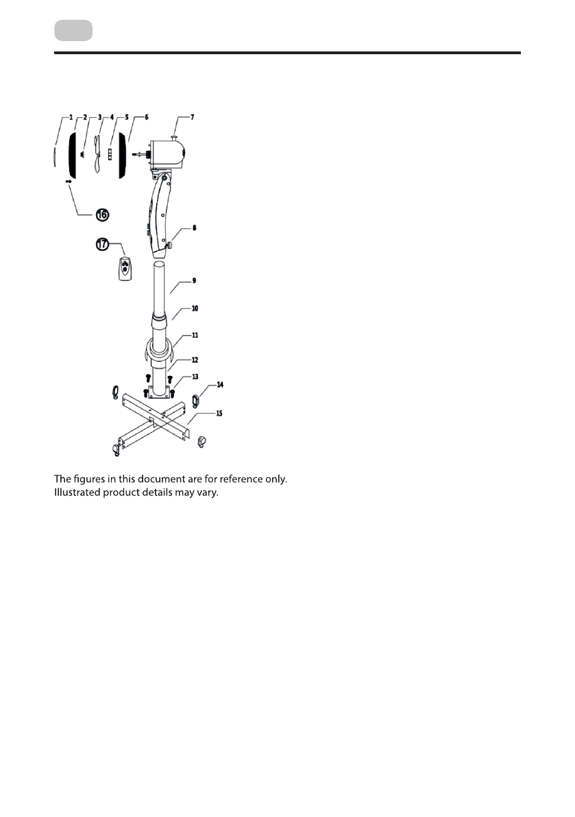
ОПИС ДЕТАЛЕЙ ВЕНТИЛЯТОРА FN-1608CW, FN-R1608CB:
1.
Декоративний ковпачок
2.
Передня захисна решітка
3.
Затискна гайка лопаті
4.
Лопаті
5.
Кільце
6.
Задня захисна решітка
7.
Двигун з кнопкою повороту
8.
Фіксуючий гвинт
9.
Подовжувач телескопічної трубки
10.
Затискач
11.
Захист основи
12.
Основна частина телескопічної трубки
13.
Гвинт ТМ5*8
14.
Ковпачки основи
15.
Основа
16.
Гвинт ТМ2,5*10
17.
Пульт керування для моделі
FN-R1608CB
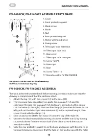
FN-1608CW, FN-R1608CB ASSEMBLE PARTS NAME:
1. Сover
2. Front protective guard
3. Blade screw
4. Blade
5. Nut
6. Rear protective guard
7. Motor with turn button
8. Fixing screw
9. Telescopic tube extension
10. Telescopic tube lock
11. Base cover
12. Telescopic tube main part
13. Screw ТМ5*8
14. Base caps
15. Base
16. Screw ТМ2.5*10
17. Remote control for FN-R1608CB
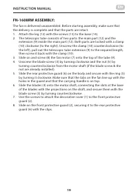
FN-1608CW, FN-R1608CB ASSEMBLY:
The fan is delivered unassembled. Before starting assembly, make sure that the
delivery is complete and that the parts are intact.
1. Attach the leg (12) with the screws (13) to the base (15).
2. The telescopic tube consists of two parts: the main part (12) and the
extension (9) inside the main part (12). Both parts are locked with a clamp
(10) clockwise (to the right). Unscrew the clamp (10) counterclockwise (to the
left), pull out the telescopic tube extension (9) to the required length, then
screw it back with the clamp (10).
3. Slide on and screw (8) the fan motor (7) onto the top of the tube (9).
4. Unscrew the blade screw (3) by turning clockwise and the nut (5) by turning
counterclockwise from the motor shaft (if the blade screw & the nut are
already installed).
5. Slide the rear protective guard (6) on the body and secure with the ring (5) by
turning it clockwise. Make sure that the tabs on the fan line up with the holes
3-
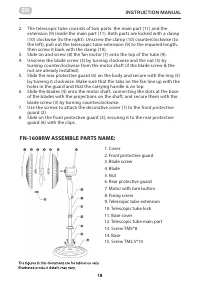
Assemble Parts Name
1. cover
2. Front guard
3. Blade Screw
4. Blade
5. Nut
6. Rear Guard
7. Panel
8. Screws
9. Into pipe
10. Pipe Lock
11. Foot cover
12. Out Pipe
13. Screw TM 5*8
14.
Foot plastic
15. Cross Base
16. Screw TM2.5*10
17. Remote
Picture 1 . Structure of Picture
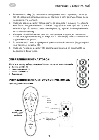
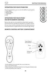
4- OPERATION FOR YOUR STAND FAN
Press the speed button you can select the different speed options:
3--HIGH SPEED
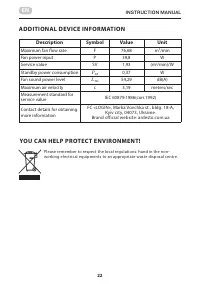
Характеристики

Остались вопросы?Не нашли свой ответ в руководстве или возникли другие проблемы? Задайте свой вопрос в форме ниже с подробным описанием вашей ситуации, чтобы другие люди и специалисты смогли дать на него ответ. Если вы знаете как решить проблему другого человека, пожалуйста, подскажите ему :)
