
Варочная панель MBS PG-904 - инструкция пользователя по применению, эксплуатации и установке на русском языке. Мы надеемся, она поможет вам решить возникшие у вас вопросы при эксплуатации техники.
Если остались вопросы, задайте их в комментариях после инструкции.
"Загружаем инструкцию", означает, что нужно подождать пока файл загрузится и можно будет его читать онлайн. Некоторые инструкции очень большие и время их появления зависит от вашей скорости интернета.


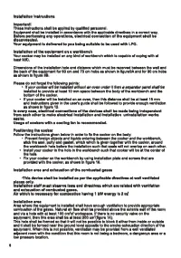


Installation Instructions
Important!
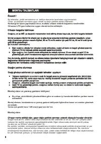
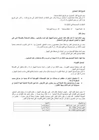
These instructions shall be applied by qualified personnel.
Equipment shall be installed in accordance with the applicable directives in a correct way.
Before performing any operations, electrical connection of the equipment shall be
disconnected.
Your equipment is delivered to you being suitable to be used with LPG.
Installation of the equipment on a workbench
Your cooker may be installed on any kind of workbench which is capable of coping with at
o
least 90C.
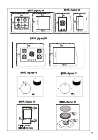
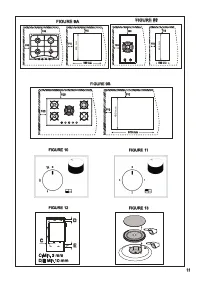
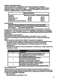
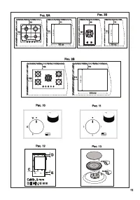
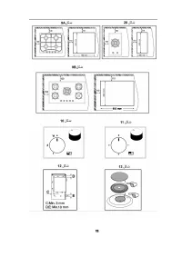
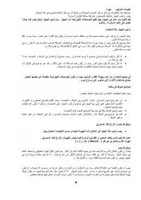
Dimensions of the installation hole and distance which must be rezerved between the wall and
the back of the
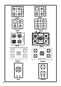
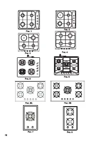
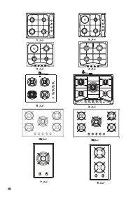
equipment for 60 cm and 70 cm hobs as shown in figure
9
A and for 90 cm hobs
as shown in figure
9
B
.
Please do not forget the following points:
·
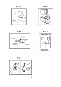
If your cooker will be installed without an oven under it then a separator panel shall be
installed to provide at least 10 mm space between the body of the workbench and the
bottom of the cooker.
·
If your cooker will be installed on an oven, then this distance shall be at least 15 mm
and instructions given in the user's guide shall be followed to provide enough ventilation
as shown in figure 12.
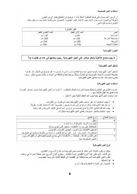
In every case, electrical connections of the devices shall be made being independent
from each other to make electrical installation and installation uninstallation works
easier.
Usage of cookers with a cooling fan is recommended.
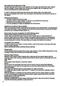
Positioning the cooker
Follow the instructions given below in order to fix the cooker on the body:
·
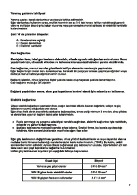
Prevent foreign objects and liquids entering between the cooker and the workbench,
stick the seal, putty and gasket, which
which is given together with the cooker, around
the workbench hole before the installation such that seals will not overlap on each other.
·
Install your cooker in the hole in the workbench such that cooker will be at the center of
the hole.
·
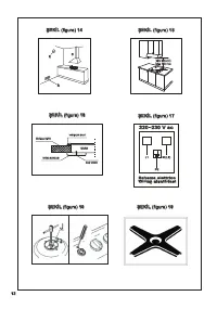
Fix your cooker on the workbench by using installation plate and screws that are
provided with the cooker, as shown in figure 16.
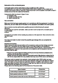
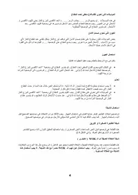
Installation area and exhaustion of the combusted gases
·
This device shall be installed as per the applicable directives at well ventilated
places only.
Installation staff must observe laws and directives which are related with ventilation
and exhaustion of combusted gases.
3
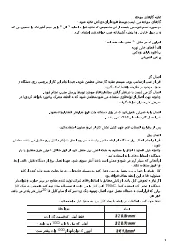
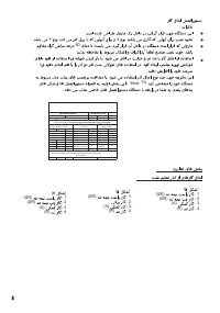
Air which is necessary for combustion having 1 kW energy is 2 m.
Installation area
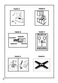
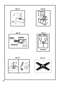
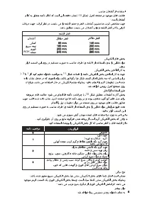
Area where the equipment is installed shall have enough ventilation to provide appropriate
combustion of the gases. Natural air flow shall be provided above the outside wall of the room
2
and via a hole with at least 100 cm of workspace. If there is no security valve on the
2
equipment, then this area shall be at least 200 cm (figure 14).
This hole shall be formed so that it will not be possible to block it either from inside or outside
and it shall be formed near the ground level opposite to the smoke exhaustion direction of the
equipment. When this is not possible, ventilation may be provided from a well ventilated
adjacent room with the condition that this room is not being a bedroom, a dangeroys area or a
low pressure location.
Installation Instructions
Important!
Before performing any operations, electrical connection of the equipment shall be
disconnected.
Your equipment is delivered to you being suitable to be used with LPG.
Installation of the equipment on a workbench
In every case, electrical connections of the devices shall be made being independent
from each other to make electrical installation and installation uninstallation works
easier.
Usage of cookers with a cooling fan is recommended.
Positioning the cooker
Installation area and exhaustion of the combusted gases
This device shall be installed as per the applicable directives at well ventilated
places only.
Installation staff must observe laws and directives which are related with ventilation
and exhaustion of combusted gases.
Air which is necessary for combustion having 1 kW energy is 2 m.
Installation area
These instructions shall be applied by qualified personnel.
Equipment shall be installed in accordance with the applicable directives in a correct way.
Your cooker may be installed on any kind of workbench which is capable of coping with at
least 90C.
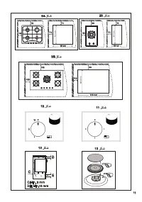
Dimensions of the installation hole and distance which must be rezerved between the wall and
the back of the
9
9 .
Please do not forget the following points:
If your cooker will be installed without an oven under it then a separator panel shall be
installed to provide at least 10 mm space between the body of the workbench and the
bottom of the cooker.
If your cooker will be installed on an oven, then this distance shall be at least 15 mm
and instructions given in the user's guide shall be followed to provide enough ventilation
as shown in figure 12.
Follow the instructions given below in order to fix the cooker on the body:
Prevent foreign objects and liquids entering between the cooker and the workbench,
which is given together with the cooker, around
the workbench hole before the installation such that seals will not overlap on each other.
Install your cooker in the hole in the workbench such that cooker will be at the center of
the hole.
Fix your cooker on the workbench by using installation plate and screws that are
provided with the cooker, as shown in figure 16.
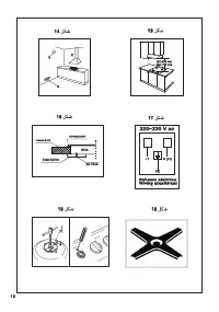
Area where the equipment is installed shall have enough ventilation to provide appropriate
combustion of the gases. Natural air flow shall be provided above the outside wall of the room
and via a hole with at least 100 cm of workspace. If there is no security valve on the
equipment, then this area shall be at least 200 cm (figure 14).
This hole shall be formed so that it will not be possible to block it either from inside or outside
and it shall be formed near the ground level opposite to the smoke exhaustion direction of the
equipment. When this is not possible, ventilation may be provided from a well ventilated
adjacent room with the condition that this room is not being a bedroom, a dangeroys area or a
low pressure location.
o
2
2
equipment for 60 cm and 70 cm hobs as shown in figure A and for 90 cm hobs
as shown in figure B
stick the seal, putty and gasket, which
·
·
·
·
·
·
3
6
6
Характеристики

Остались вопросы?Не нашли свой ответ в руководстве или возникли другие проблемы? Задайте свой вопрос в форме ниже с подробным описанием вашей ситуации, чтобы другие люди и специалисты смогли дать на него ответ. Если вы знаете как решить проблему другого человека, пожалуйста, подскажите ему :)


