
Шуруповерты Metabo SE 4000 620045000 - инструкция пользователя по применению, эксплуатации и установке на русском языке. Мы надеемся, она поможет вам решить возникшие у вас вопросы при эксплуатации техники.
Если остались вопросы, задайте их в комментариях после инструкции.
"Загружаем инструкцию", означает, что нужно подождать пока файл загрузится и можно будет его читать онлайн. Некоторые инструкции очень большие и время их появления зависит от вашей скорости интернета.


ENGLISH
en
10
and comes into contact with your eyes, wash them
with clean water and seek medical attention
immediately!
LED lights (6): Do not observe the LED radiation
directly with optical instruments.
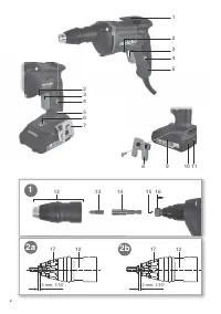
See page 2.
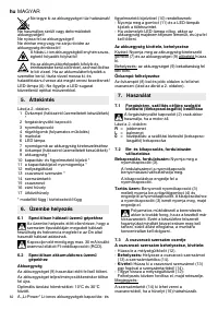
1 Belt hook (mains powered tools) *
2 Rotation selector switch
3 Trigger switch
4 Lock button (continuous operation)
5 Handle
6 LED lights
7 Battery pack release button
8 Belt hook (cordless tools)*
9 Battery pack *
10 Capacity and signal indicator *
11 Capacity indicator button *
12 Depth stop
13 screwdriver bit*
14 Bit holder
15 Screwdriver spindle
16 Closure sleeve
17 Stop sleeve
* depending on the model / features
a
6.1
For mains powered machines only
Before plugging in, check that the rated mains
voltage and mains frequency, as stated on the
type plate match your power supply.
Always install an RCD with a maximum trip
current of 30 mA upstream.
6.2
For cordless machines only
Battery pack
Charge the battery pack (9) before use.
If performance diminishes, recharge the battery
pack.
The ideal storage temperature is between 10°C and
30°C.
Li-Ion battery packs "Li-Power" have a capacity and
signal indicator (10):
- Press the button (11), the LEDs indicate the
charge level.
- If one LED is flashing, the battery pack is almost
flat and must be recharged.
Removing and inserting the battery pack
Removal: Press the battery pack release button (7)
and pull the battery pack (9) forwards.
To insert: Slide the battery pack (9) in until it
engages.
Installation of belt hook
The belt hook (8) may be screwed into place on the
left or the right (see illustration, page 2).
7.1
Setting the direction of rotation,
engaging the transporting safety device
(switch-on lock)
Do not activate rotation selector switch (2)
unless the motor has completely stopped.
See page 2:
R
= Clockwise setting
L
= Counter-clockwise setting
0
= Central position: transportation lock setting
(switch-on lock)
7.2
On/Off switch, modifying the speed
Switching on, speed:
press the trigger switch (3).
Press in the trigger to increase the rotational
speed.
To switch off release the trigger switch.
Continuous activation:
With the trigger (3)
pressed, push in the locking button (4) and
release the trigger. Press and release the trigger
again (3) to switch off.
In continuous operation, the machine
continues running if it is forced out of your
hands. Therefore, always hold the machine with
both hands using the handles provided, stand
securely and concentrate.
7.3
Screwdriver bit change
Inserting and removing the screwdriver bit:
- Remove the depth stop (12).
-
Insert:
Insert the screwdriver bit (13) in the bit
holder (14).
-
Remove:
Pull the screwdriver bit (13) from the bit
holder (14) using a pliers.
- Attach the depth stop (12) again:
turn and engage in position when mounted.
Note:
The bit holder (14) may be removed from the
screwdriver spindle if the sleeve (16) is pulled back.
Never use 25 mm long
screwdriver
bits (13) in the screwdriver spindle
(15)! Removal is not possible! Only
use the bit holder (14)!
7.4
Working with depth stop
See page 2, illustration 2 a and 2 b.
To preset the screw insertion depth, one of the
screws to be inserted is fitted on the screwdriver bit
(13). Set the depth stop (12) by turning as follows:
a) Screws with heads designed to sit on top of the
material (socket-head screws, oval head screws,
hex screws):
the surface area of the screw head is 2 mm outside
the stop sleeve (17).
b) Flat head screws:
the area of the screw head is 2 mm outside the stop
sleeve (17).
Insert a screw as a test. Correct the screw depth if
necessary:
5. Overview
6. Commissioning
7. Use


