
Шуруповерты Makita DHP481RTE - инструкция пользователя по применению, эксплуатации и установке на русском языке. Мы надеемся, она поможет вам решить возникшие у вас вопросы при эксплуатации техники.
Если остались вопросы, задайте их в комментариях после инструкции.
"Загружаем инструкцию", означает, что нужно подождать пока файл загрузится и можно будет его читать онлайн. Некоторые инструкции очень большие и время их появления зависит от вашей скорости интернета.


8
Adjusting the fastening torque
(screwdriver mode "
")
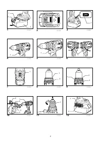
Fig.9
The fastening torque can be adjusted in 21 steps by
turning the adjusting ring so that its graduations are
aligned with the pointer on the tool body.
First, slide the action mode change lever to the position
of
symbol.
The fastening torque is minimum when the number 1 is
aligned with the pointer, and maximum when the
marking is aligned with the pointer. The clutch will slip at
various torque levels when set at the number 1 to 21.
Before actual operation, drive a trial screw into your
material or a piece of duplicate material to determine
which torque level is required for a particular application.
NOTE:
•
The adjusting ring does not lock when the pointer
is positioned only halfway between the
graduations.
ASSEMBLY
CAUTION:
•
Always be sure that the tool is switched off and the
battery cartridge is removed before carrying out
any work on the tool.
Installing side grip (auxiliary handle)
Fig.10
Always use the side grip to ensure operating safety.
Insert the side grip so that the groove on the arm fit in
one of the counter parts on the tool. Then tighten the
grip by turning clockwise.
Depending the operations, you can install the side grip
either right or left side of the tool.
Installing or removing driver bit or drill bit
Fig.11
Turn the sleeve counterclockwise to open the chuck
jaws. Place the bit in the chuck as far as it will go. Turn
the sleeve clockwise to tighten the chuck. To remove
the bit, turn the sleeve counterclockwise.
Installing bit holder
Fig.12
Fit the bit holder into the protrusion at the tool foot on
either right or left side and secure it with a screw.
When not using the driver bit, keep it in the bit holders.
Bits 45 mm long can be kept there.
Adjustable depth rod
Fig.13
The adjustable depth rod is used to drill holes of uniform
depth. Loosen the clamp screw, set to desired position,
then tighten the clamp screw.
Hook
Fig.14
The hook is convenient for temporarily hanging the tool.
This can be installed on either side of the tool.
To install the hook, insert it into a groove in the tool
housing on either side and then secure it with a screw.
To remove, loosen the screw and then take it out.
OPERATION
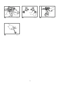
Fig.15
Hammer drilling operation
CAUTION:
•
There is a tremendous and sudden twisting force
exerted on the tool/bit at the time of hole break-
through, when the hole becomes clogged with
chips and particles, or when striking reinforcing
rods embedded in the concrete. Always use the
side grip (auxiliary handle) and firmly hold the tool
by both side grip and switch handle during
operations. Failure to do so may result in the loss
of control of the tool and potentially severe injury.
First, slide the action mode change lever so that it
points to the
marking. The adjusting ring can be
aligned in any torque levels for this operation.
Be sure to use a tungsten-carbide tipped bit.
Position the bit at the desired location for the hole, then
pull the switch trigger. Do not force the tool. Light
pressure gives best results. Keep the tool in position
and prevent it from slipping away from the hole.
Do not apply more pressure when the hole becomes
clogged with chips or particles. Instead, run the tool at
an idle, then remove the bit partially from the hole. By
repeating this several times, the hole will be cleaned out
and normal drilling may be resumed.
Blow-out bulb (optional accessory)
Fig.16
After drilling the hole, use the blow-out bulb to clean the
dust out of the hole.
Screwdriving operation
First, slide the action mode change lever so that it points
to the
marking. Adjust the adjusting ring to the proper
torque level for your work. Then proceed as follows.
Place the point of the driver bit in the screw head and
apply pressure to the tool. Start the tool slowly and then
increase the speed gradually. Release the switch trigger
as soon as the clutch cuts in.
NOTE:
•
Make sure that the driver bit is inserted straight in
the screw head, or the screw and/or bit may be
damaged.
•
When driving wood screw, predrill a pilot hole 2/3
the diameter of the screw. It makes driving easier
and prevents splitting of the workpiece.
Характеристики

Остались вопросы?Не нашли свой ответ в руководстве или возникли другие проблемы? Задайте свой вопрос в форме ниже с подробным описанием вашей ситуации, чтобы другие люди и специалисты смогли дать на него ответ. Если вы знаете как решить проблему другого человека, пожалуйста, подскажите ему :)


