
Шуруповерты Makita DF0300+D-58833 - инструкция пользователя по применению, эксплуатации и установке на русском языке. Мы надеемся, она поможет вам решить возникшие у вас вопросы при эксплуатации техники.
Если остались вопросы, задайте их в комментариях после инструкции.
"Загружаем инструкцию", означает, что нужно подождать пока файл загрузится и можно будет его читать онлайн. Некоторые инструкции очень большие и время их появления зависит от вашей скорости интернета.


7 ENGLISH
FUNCTIONAL
DESCRIPTION
CAUTION:
Always be sure that the tool is
switched off and unplugged before adjusting or
checking function on the tool.
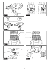
Switch action
►
Fig.1:
1.
Switch trigger
2.
Lock button
CAUTION:
Before plugging in the tool, always
check to see that the switch trigger actuates
properly and returns to the "OFF" position when
released.
CAUTION:
Switch can be locked in “ON” posi-
tion for ease of operator comfort during extended
use. Apply caution when locking tool in “ON”
position and maintain firm grasp on tool.
To start the tool, simply pull the switch trigger. Tool
speed is increased by increasing pressure on the switch
trigger. Release the switch trigger to stop.
For continuous operation, pull the switch trigger, push
in the lock button and then release the switch trigger.
To stop the tool from the locked position, pull the switch
trigger fully, then release it.
Reversing switch action
►
Fig.2:
1.
Reversing switch lever
CAUTION:
Always check the direction of
rotation before operation.
CAUTION:
Use the reversing switch only after
the tool comes to a complete stop.
Changing the
direction of rotation before the tool stops may dam
-
age the tool.
This tool has a reversing switch to change the direction
of rotation. Depress the reversing switch lever from the
A side for clockwise rotation or from the B side for coun-
terclockwise rotation.
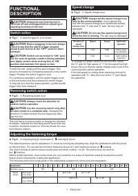
Speed change
►
Fig.3:
1.
Speed change lever
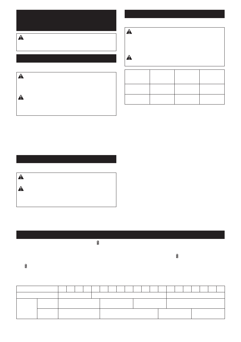
CAUTION:
Always set the speed change lever
fully to the correct position.
If you operate the
tool with the speed change lever positioned halfway
between the "1" side and "2" side, the tool may be
damaged.
CAUTION:
Do not use the speed change lever
while the tool is running.
The tool may be damaged.
Position of
speed
change lever
Speed
Torque
Applicable
operation
1
Low
High
Heavy load-
ing operation
2
High
Low
Light loading
operation
To change the speed, switch off the tool first. Select
the "2" side for high speed or "1" for low speed but high
torque. Be sure that the speed change lever is set to the
correct position before operation.
If the tool speed is coming down extremely during the
operation with "2", slide the lever to the "1" and restart
the operation.
Adjusting the fastening torque
►
Fig.4:
1.
Adjusting ring
2.
Graduation
3.
marking
4.
Arrow
The fastening torque can be adjusted in 21 levels by turning the adjusting ring. Align the graduations with the arrow
on the tool body. You can get the minimum fastening torque at 1 and maximum torque at
marking.
The clutch will slip at various torque levels when set at the number 1 to 20. The clutch does not work at
the
marking.
Before actual operation, drive a trial screw into your material or a piece of duplicate material to determine which
torque level is required for a particular application.
The following shows the rough guide of the relationship between the screw size and graduation.
Graduation
1
2
3
4
5
6
7
8
9
10 11 12 13 14 15 16 17 18 19 20
Machine screw
M4
M5
M6
Wood
screw
Soft wood
(e.g. pine)
–
ɸ
3.5 x 22
ɸ
4.1 x 38
–
Hard wood
(e.g. lauan)
–
ɸ
3.5 x 22
ɸ
4.1 x 38
–
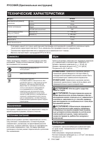
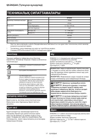
Характеристики

Остались вопросы?Не нашли свой ответ в руководстве или возникли другие проблемы? Задайте свой вопрос в форме ниже с подробным описанием вашей ситуации, чтобы другие люди и специалисты смогли дать на него ответ. Если вы знаете как решить проблему другого человека, пожалуйста, подскажите ему :)


