
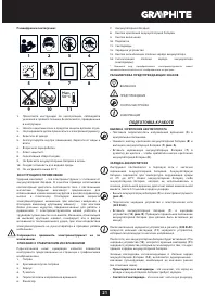
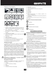
Шуруповерты GRAPHITE Energy+ 58g012 - инструкция пользователя по применению, эксплуатации и установке на русском языке. Мы надеемся, она поможет вам решить возникшие у вас вопросы при эксплуатации техники.
Если остались вопросы, задайте их в комментариях после инструкции.
"Загружаем инструкцию", означает, что нужно подождать пока файл загрузится и можно будет его читать онлайн. Некоторые инструкции очень большие и время их появления зависит от вашей скорости интернета.


13
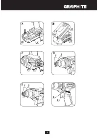
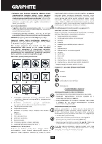
BAT TERY LE VEL INDIC ATION
The batter y is equipped with signalisation of the batter y level (3
LED diodes) (
14
). To check batter y level status, press the button
for batter y level indication (
13
) (
fig. C
). When all diodes are lit,
the batter y level is high. When 2 diodes are on, the batter y is
par tially discharged. When only one diode is lit, the batter y is
discharged and must be recharged.
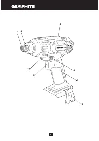
S P I N D L E B R A K E
Drill is equipped with electronic brake that stops the spindle
immediately after the switch button (
9
) is released. The brake
ensures precision when screwing or drilling and prevents free
spindle rotation after switching off.
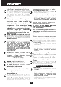
OPERATION / SETTINGS
S W I TC H I N G O N / S W I TC H I N G O F F
Switching on
– press the switch button (
9
).
Switching off
– release the switch button (
9
).
Each time the switch button (
9
) is pressed, the LED diode (
10
)
lights up to illuminate the workplace.
ROTATIONAL SPEED CONTROL
Increase or reduce pressure on the switch button (
9
) to adjust
rotational speed while operating. Speed control allows for soft
star t, which provides working control during tightening and
undoing bolts.
C I R C U M F E R E N T I A L I M PAC T AC T I O N
The tool rotates the spindle when tightening, and creates
circumferential impact. Impact action actuates automatically
when the load increases. Then a high peak torque is applied.
Keep watching the screw or bolt for full control over tightening.
Keep control over tightening force by adjusting rotational speed.
WO R K I N G TO O L I N S TA L L AT I O N
•
Pull away the fixing sleeve of the tool chuck (
2
) (
fig. D
) against
the spring force.
•
Inser t working tool shank into the tool chuck (
1
) and slide it in
to mechanical stop (it may be necessar y to turn the working
tool so it can reach appropriate position).
•
Release the fixing sleeve of the tool chuck (
2
), it will finally lock
the working tool. The fixing sleeve of the tool chuck (
2
) will
return to its position (
fig. E
).
Deinstallation of the tool is similar to installation, only the
sequence of actions is reversed.
Use additional driver bit adapter with shor t driver bits.
RIGHT-LEFT DIRECTION OF ROTATION
Choose direction of spindle rotation with the direction selector
switch (
5)
(
fig. F
).
Clockwise rotation
– set the switch (
5
) to the extreme left
position.
Counter-clockwise rotation
– set the switch (
5
) to the extreme
right position.
* In cer tain cases position of the switch related to rotation may be different
than specified. Please refer to graphic signs located on the switch or tool
body.
Safe position of the direction selector switch (
5
) is in the middle,
it prevents accidental star ting of the power tool.
•
When the switch is in this position, the power tool cannot be
star ted.
•
Use this position of the switch to change bits.
•
Before star ting the tool make sure the position of the direction
selector switch (
5
) is correct.
Do not change direction of rotation when the spindle of the
power tool is rotating.
Long lasting operation at low rotational speed of the
spindle may cause motor overheating. Long lasting drilling
at low rotational speed of the spindle may cause motor
overheating.
H O L D E R
The power tool provides convenient holder (
6
) that allows to e.g.
hang the tool on a tool belt when working at heights.
OPERATION AND MAINTENANCE
M A I N T E N A N C E A N D S TO R AG E
•
Cleaning the device after each use is recommended.
•
Do not use water or any other liquid for cleaning.
•
Clean the power tool, batter y and charger with a dr y cloth or
blow through with compressed air at low pressure.
•
Do not use any cleaning agents or solvents, they may damage
plastic par ts.
•
Clean ventilation holes in the motor casing regularly to
prevent device overheating.
•
In case of excessive commutator sparking, have the technical
condition of carbon brushes of the motor checked by a
qualified person.
•
Store the power tool and its equipment in a dr y place, beyond
reach of children.
•
Store the device with the batter y removed.
All defects should be repaired by ser vice workshop authorized
by the manufacturer.
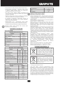
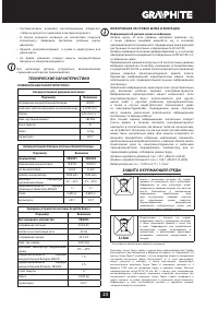
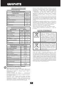
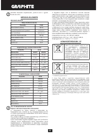
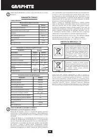
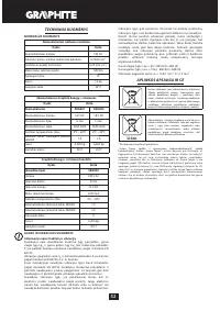
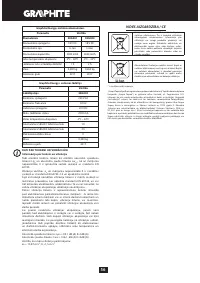
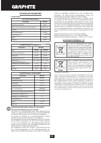
TECHNICAL PARAMETERS
R AT E D PA R A M E T E R S
Cordless impact driver
Parameter
Value
Battery voltage
18V DC
Range of idle rotational speed
0-2200 min
-1
Tool chuck
6,35 mm (¼ ‘’)
Max. torque
180 Nm
Protection class
III
Weight 1,2
kg
Year of production
2017
Graphite Energy+ System Battery
Parameter
Value
Battery
58G001
58G004
Battery voltage
18 V DC
18 V DC
Battery type
Li-Ion
Li-Ion
Battery capacity
2000 mAh
4000 mAh
Ambient temperature range
4
0
C – 40
0
C
4
0
C – 40
0
C
Charging time for charger 58G002
1 h
2 h
Weight
0,400 kg
0,650 kg
Year of production
2017
2017


