
Шуруповерты GRAPHITE Energy+ 58g006 - инструкция пользователя по применению, эксплуатации и установке на русском языке. Мы надеемся, она поможет вам решить возникшие у вас вопросы при эксплуатации техники.
Если остались вопросы, задайте их в комментариях после инструкции.
"Загружаем инструкцию", означает, что нужно подождать пока файл загрузится и можно будет его читать онлайн. Некоторые инструкции очень большие и время их появления зависит от вашей скорости интернета.


13
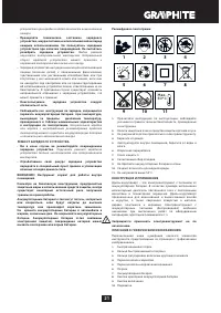
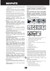
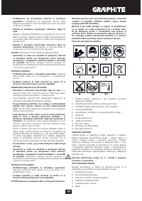
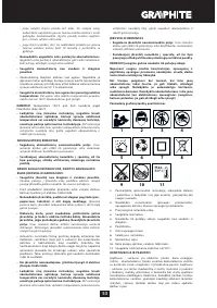
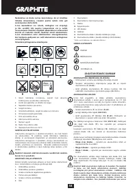
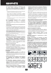
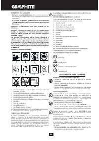
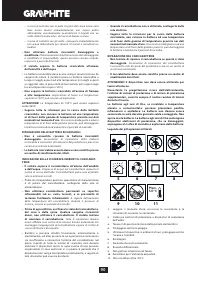
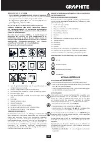
M E A N I N G O F S YM B O L S
CAUTION
WARNING
ASSEMBLY / SET TINGS
INFORMATION
PREPARATION FOR OPERATION
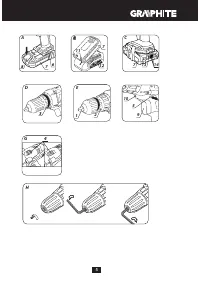
REMOVING AND INSERTING THE BAT TERY
•
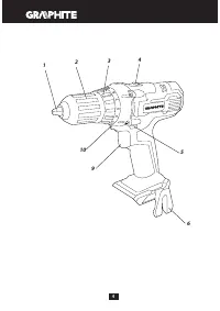
Set the direction selector switch (
5
) in middle position.
•
Push the batter y lock button (
8
) and slide out the batter y (
7
)
(
fig. A
).
•
Inser t charged batter y (
7
) into the handle holder, you should
hear when the batter y lock button (
8
) snaps.
BAT TERY CHARGING
The device is supplied with par tially charged batter y. The batter y
should be charged in ambient temperature between 4°C and
40°C. New batter y, or one that has not been used for a long
time, will reach full efficiency after approximately 3 to 5 charge/
discharge cycles.
•
Remove the batter y (
7
) from the device (
fig. A
).
•
Connect the charger to mains socket (230 V AC).
•
Slide the batter y (
7
) into the charger (
12
) (
fig. B
). Ensure the
batter y is properly fitted (pushed to the end).
When the charger is connected to a mains socket (
230 V AC
), the
green diode (
11
) on the charger turns on to indicate connected
supply.
When the batter y (
7
) is placed in the charger (
12
), the red diode
(
11
) on the charger turns on to indicate that the charging is in
progress.
Simultaneously, green diodes (
14
) of the batter y level indication
are flashing in different configurations, see description below.
• All diodes are flashing
- batter y is empty and requires
charging.
• 2 diodes are flashing
- the batter y is par tially discharged.
• 1 diode is flashing
- the batter y level is high.
Once the batter y is charged, the diode (
11
) on the charger lights
green, and all batter y level diodes (
14
) light continuously. After
some time (approx. 15 s) batter y level indication diodes (
14
) turn
off.
Do not charge the batter y for more than 8 hours. Exceeding
this time limit may cause damage to batter y cells. The charger
will not turn off automatically when the batter y is full. Green
diode on the charger will remain on. Batter y level indication
diodes turn off after some time. Disconnect power supply
before removing the batter y from the charger socket. Avoid
consecutive shor t chargings. Do not charge the batter y after
shor t use of the tool. Significant decrease of the period
between chargings indicates the batter y is used up and should
be replaced.
Batteries heat up when charging. Do not operate just
after charging – wait for the batter y to cool down to room
temperature. It will prevent batter y damage.
BAT TERY LE VEL INDIC ATION
The batter y is equipped with signalisation of the batter y level (3
LED diodes) (
14
). To check batter y level status, press the button
for batter y level indication (
13
) (
fig. C
). When all diodes are lit,
the batter y level is high. When 2 diodes are on, the batter y is
par tially discharged. When only one diode is lit, the batter y is
discharged and must be recharged.
S P I N D L E B R A K E
Drill is equipped with electronic brake that stops the spindle
immediately after the switch button (
9
) is released. The brake
ensures precision when screwing or drilling and prevents free
spindle rotation after switching off.
OPERATION / SETTINGS
S W I TC H I N G O N / S W I TC H I N G O F F
Switching on
– press the switch button (
9
).
Switching off
– release the switch button (
9
).
Each time the switch button (
9
) is pressed, the LED diode (
10
)
lights up to illuminate the workplace.
ROTATIONAL SPEED CONTROL
Increase or reduce pressure on the switch button (
9
) to adjust
drilling or driving speed while operating. Speed adjustment
allows for a soft star t, which prevents dill slipping when drilling
holes in gypsum or glaze, and allows for operation control when
driving screws in and out.
OV E R LOA D C LU TC H
Set the torque adjustment ring (
3
) in appropriate position
to permanently set overload clutch to defined torque value.
When the set torque is reached, overload clutch disconnects
automatically. It prevents from driving screws too deep or
damaging the drill.
TO RQUE ADJUSTMENT
•
Different screws and materials require different torque to be
applied.
•
The bigger the number corresponding to given position, the
bigger is the torque (
fig. D
).
•
Set the torque adjustment ring (
3
) to appropriate torque value.
•
Always star t operation with low torque.
•
Increase the torque gradually until obtaining desired results.
•
Use higher settings to undo screws.
•
When drilling, choose setting marked with the drill symbol.
The torque is the greatest with this setting.
•
Knowledge how to choose appropriate torque setting comes
with practice.
Setting the torque adjustment ring in the drilling position
deactivates the overload clutch.
WO R K I N G TO O L I N S TA L L AT I O N
•
Set the direction selector switch (
5
) in the middle position.
•
By turning the ring of the quick release chuck (
2
) counter
clockwise (see mark on the ring) you can spread jaws enough
to inser t drill or driver bit (
fig. E
).
•
To fix the working tool, turn the ring of the quick release chuck
(
2
) clockwise and tighten.
Deinstallation of the tool is similar to installation, only the
sequence of actions is reversed.
Make sure the tool position is correct when installing drill or
driver bit in the quick release chuck. Use additional magnetic
adapter as an extension when using shor t driver bits.
RIGHT-LEFT DIREC TION OF ROTATION
Choose direction of spindle rotation with the direction selector
switch (
5
) (
fig. F
).
Clockwise rotation
– set the switch (
5
) to the extreme left
position.


