
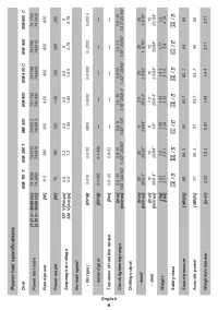
Шуруповерты DWT BM-400 C 5.1.8 - инструкция пользователя по применению, эксплуатации и установке на русском языке. Мы надеемся, она поможет вам решить возникшие у вас вопросы при эксплуатации техники.
Если остались вопросы, задайте их в комментариях после инструкции.
"Загружаем инструкцию", означает, что нужно подождать пока файл загрузится и можно будет его читать онлайн. Некоторые инструкции очень большие и время их появления зависит от вашей скорости интернета.


12
English
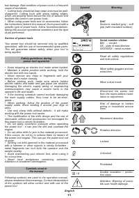
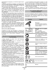
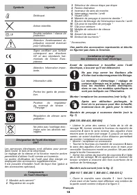
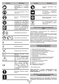
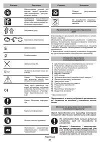
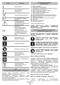
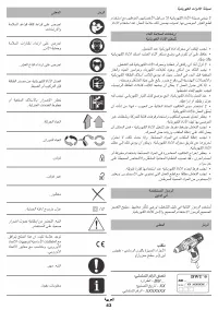
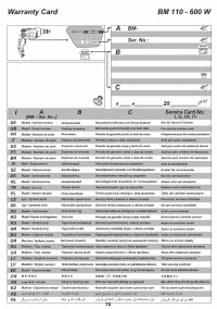
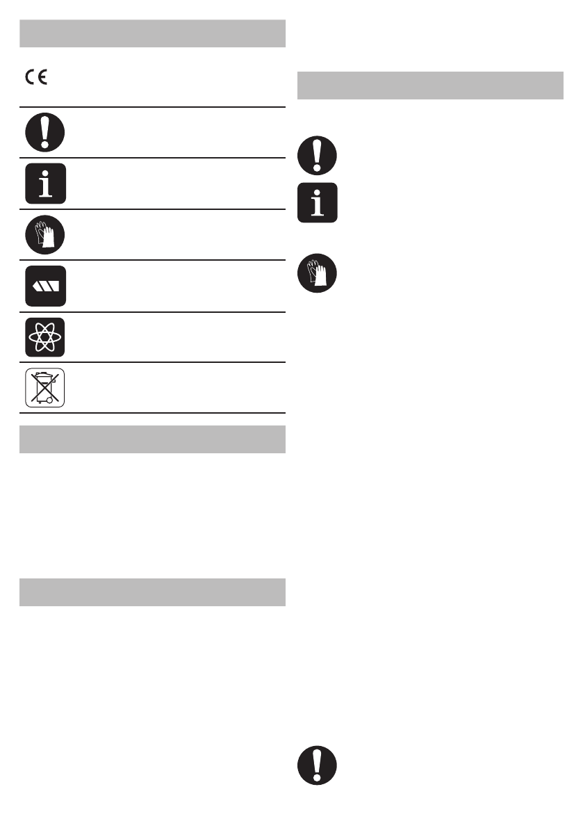
Symbol
Meaning
A sign certifying that the
product complies with es-
sential requirements of the
EU directives and harmo
-
nized EU standards.
Attention. Important.
Useful information.
Wear protective gloves.
Torque control position:
"Drilling".
Stepless speed control.
Do not dispose of the power
tool in a domestic waste
container.
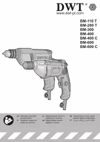
DWT
power tool designation
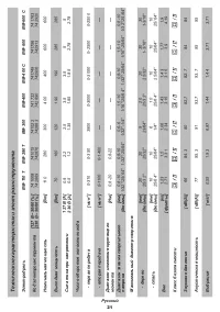
Electric drills are used for drilling in steel, wood and
ceramics.
The ability to adjust the speed and availability of the
reverse mode allows the power tool to be used as a
screwdriver.
The area of the tool application can be expanded due
to use of additional accessories.
There is a possibility of a stationary installation of the
tool by use of some special accessories.
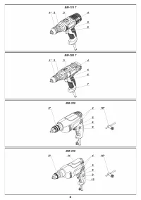
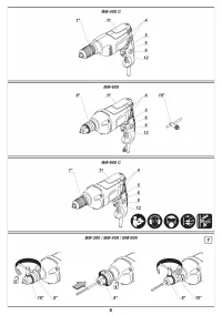
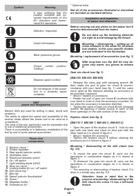
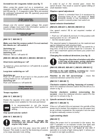
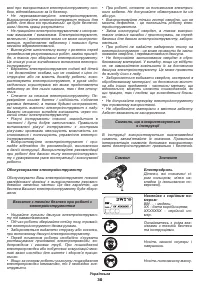
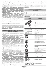
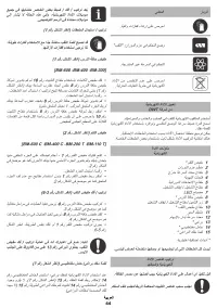
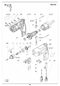
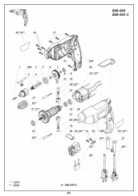
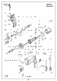
1
Power tool
components
Keyless chuck *
2
Torque regulator
3
Step speed selector switch
4
Ventilation slots
5
Rotational direction switch
6
On / off switch
7
Light-emitting diode (LED)
8
Gear rim chuck *
9
Locking button for on / off switch
10
Drill chuck key *
11
Belt clip
12
Speed selector thumbwheel
13
Screw *
14
Magnetic holder *
15
Screwdriver bit *
*
Optional extra
Not all of the accessories illustrated or described
are included as standard delivery.
Installation and regulation
of power tool elements
Before carrying out any works on the power tool it
must be disconnected from the mains.
Do not draw up the fastening elements
too tight to avoid damaging the thread.
Mounting / dismounting / setting-up of
some elements is the same for all power
tool models, in this case specific models
are not indicated in the illustration.
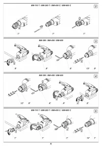
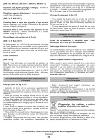
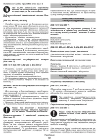
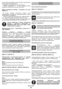
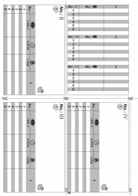
Mounting / replacement of accessories (see fig. 1)
With long-term use the drill bit may be-
come very warm; use gloves to remove
it.
Gear rim chuck (see fig. 1)
[BM-300, BM-400, BM-600]
•
Release the cams grip with clamping wrench
10
,
then rotate the quill of gear rim chuck
8
counter-
clockwise with your hand (see fig. 1) until the cams
move apart at the distance allowing an accessory to
be mounted / replaced.
•
Mount / replace an accessory.
•
Rotate the quill of gear rim chuck
8
clockwise with
your hand in order to lock the accessory mounted. Do
not allow the accessory to become distorted.
•
Tighten the cams of gear rim chuck
8
with clamping
wrench
10
applying a similar torque to each of the
three openings on the side surface of the chuck.
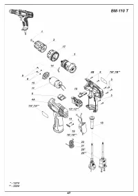
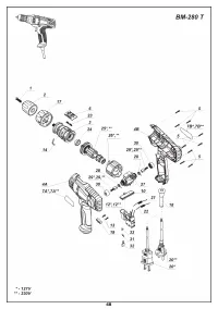
Keyless chuck (see fig. 2)
[BM-110 T, BM-280 T, BM-400 C, BM-600 C]
• Open the jaws of the keyless chuck
1
- hold its rear
part with one hand and rotate its front part with the
other hand as it is shown in figure 2.
•
Mount / replace the accessory.
•
Tighten the keyless chuck
1
without skewing the
accessory as it is shown in figure 2.
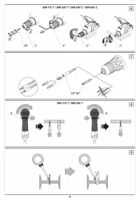
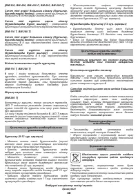
Mounting / dismounting of the drill chuck (see
fig. 3-6)
•
To mount the gear rim chuck
8
, carry out the
operations in consecutive stages as it is shown in
figure 3.
•
To dismount the gear rim chuck
8
, carry out the
operations in consecutive stages as it is shown in
figure 4.
•
The mounting or dismounting of keyless chuck
1
is
done is a similar way, see fig. 5-6.
Attention: keep in mind that in the
process of mounting / dismounting of the
drill chuck the screw 13 has a left-hand
thread.


