
Шуруповерты Black+Decker KR806K - инструкция пользователя по применению, эксплуатации и установке на русском языке. Мы надеемся, она поможет вам решить возникшие у вас вопросы при эксплуатации техники.
Если остались вопросы, задайте их в комментариях после инструкции.
"Загружаем инструкцию", означает, что нужно подождать пока файл загрузится и можно будет его читать онлайн. Некоторые инструкции очень большие и время их появления зависит от вашей скорости интернета.


6
ENGLISH
working with wood, especially oak, beech and
MDF.)
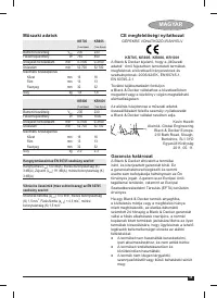
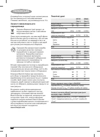
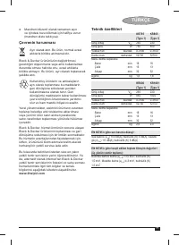
Vibration
The declared vibration emission values stated
in the technical data and the declaration of
conformity have been measured in accordance
with a standard test method provided by EN 60745
and may be used for comparing one tool with
another. The declared vibration emission value
may also be used in a preliminary assessment of
exposure.
Warning!
The vibration emission value during
actual use of the power tool can differ from the
declared value depending on the ways in which
the tool is used. The vibration level may increase
above the level stated.
When assessing vibration exposure to determine
safety measures required by 2002/44/EC to
protect persons regularly using power tools in
employment, an estimation of vibration exposure
should consider, the actual conditions of use and
the way the tool is used, including taking account
of all parts of the operating cycle such as the
times when the tool is switched off and when it is
running idle in addition to the trigger time.
Labels on tool
The following pictograms are shown on the tool:
Warning!
To reduce the risk of injury, the
user must read the instruction manual.
Electrical safety
This tool is double insulated; therefore
no earth wire is required. Always check
that the power supply corresponds to the
voltage on the rating plate.
♦
If the supply cord is damaged, it must be
replaced by the manufacturer or an authorised
Black & Decker Service Centre in order to
avoid a hazard.
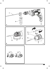
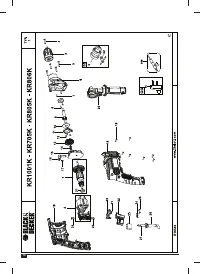
Features
This tool includes some or all of the following
features.
1. Variable speed switch
2. Lock-on
button
3. Variable speed control knob
4. Forward/reverse
switch
5. Drilling mode selector
6. Chuck
7. Depth
stop
8. Side
handle
Assembly
Warning!
Before assembly, make sure that the
tool is switched off and unplugged.
Fitting the side handle and depth stop
(
fi
g. A)
♦
Turn the grip counterclockwise until you can
slide the side handle (8) onto the front of the
tool.
♦
Rotate the side handle into the desired
position.
♦
Insert the depth stop (7) into the mounting
hole as shown.
♦
Set the drilling depth as described below.
♦
Tighten the side handle by turning the grip
clockwise.
Setting the drilling depth (
fi
g. A)
♦
Slacken the side handle (8) by turning the grip
counterclockwise.
♦
Set the depth stop (7) to the desired position.
The maximum drilling depth is equal to the
distance between the tip of the drill bit and the
front end of the depth stop.
♦
Tighten the side handle by turning the grip
clockwise.
Fitting an accessory (
fi
g. B & C)
Keyless chuck with spindle lock (Where
supplied) (
fi
g. B)
♦
Open the chuck by turning the sleeve (9)
counterclockwise.
♦
Insert the bit shaft (10) into the chuck.
♦
Tighten the chuck by turning the sleeve
clockwise.
Keyed chuck (Where supplied) (
fi
g. C)
♦
Open the chuck by turning the sleeve (11)
counterclockwise.
♦
Insert the bit shaft (10) into the chuck.
♦
Insert the chuck key (12) into each hole (13) in
the side of the chuck and turn clockwise until
tight.
Removing and re
fi
tting the chuck (
fi
g. D)
♦
Open the chuck as far as possible.
♦
Remove the chuck retaining screw, located
in the chuck, by turning it clockwise using
a screwdriver.
♦
Tighten an Allen key into the chuck and strike
it with a hammer as shown.
♦
Remove the Allen key.


