
Шлифмашины Makita GA5050R - инструкция пользователя по применению, эксплуатации и установке на русском языке. Мы надеемся, она поможет вам решить возникшие у вас вопросы при эксплуатации техники.
Если остались вопросы, задайте их в комментариях после инструкции.
"Загружаем инструкцию", означает, что нужно подождать пока файл загрузится и можно будет его читать онлайн. Некоторые инструкции очень большие и время их появления зависит от вашей скорости интернета.


11 ENGLISH
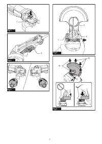
Installing or removing wheel guard
WARNING:
When using a depressed center
wheel, flap disc, flex wheel or wire wheel brush,
the wheel guard must be fitted on the tool so that
the closed side of the guard always points toward
the operator.
WARNING:
Make sure that the wheel guard is
securely locked by the lock lever with one of the
holes on the wheel guard.
WARNING:
When using an abrasive cut-off
/ diamond wheel, be sure to use only the special
wheel guard designed for use with cut-off wheels.
(In some European countries, when using a diamond
wheel, the ordinary guard can be used. Follow the
regulations in your country.)
For depressed center wheel, flap disc,
flex wheel, wire wheel brush / abrasive
cut-off wheel, diamond wheel
1.
While pushing the lock lever, mount the wheel
guard with the protrusions on the wheel guard aligned
with the notches on the bearing box.
►
Fig.4:
1.
Lock lever
2.
Notch
3.
Protrusion
2.
While pushing the lock lever toward A, hold down
the portions B of the wheel guard as shown in the
figure.
►
Fig.5:
1.
Wheel guard
2.
Hole
NOTE:
Push down the wheel guard straight.
Otherwise, you cannot secure the wheel guard.
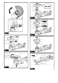
3.
While pushing the lock lever, rotate the wheel
guard toward C, and then, change the angle of the
wheel guard according to the work so that the operator
can be protected. Align the lock lever with one of the
holes in the wheel guard, and then release the lock
lever to lock the wheel guard.
►
Fig.6:
1.
Wheel guard
2.
Hole
To remove wheel guard, follow the installation proce-
dure in reverse.
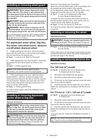
Installing or removing depressed
center wheel or flap disc
Optional accessory
WARNING:
When using a depressed center
wheel or flap disc, the wheel guard must be fitted
on the tool so that the closed side of the guard
always points toward the operator.
CAUTION:
Make sure that the mounting part
of the inner flange fits into the inner diameter of
the depressed center wheel / flap disc perfectly.
Mounting the inner flange on the wrong side may
result in the dangerous vibration.
Mount the inner flange onto the spindle.
Make sure to fit the dented part of the inner flange onto
the straight part at the bottom of the spindle.
Fit the depressed center wheel / flap disc on the inner
flange and screw the lock nut onto the spindle.
►
Fig.7:
1.
Lock nut
2.
Depressed center wheel
3.
Inner flange
4.
Mounting part
To tighten the lock nut, press the shaft lock firmly so
that the spindle cannot revolve, then use the lock nut
wrench and securely tighten clockwise.
►
Fig.8:
1.
Lock nut wrench
2.
Shaft lock
To remove the wheel, follow the installation procedure
in reverse.
Installing or removing flex wheel
Optional accessory
WARNING:
Always use supplied guard when
flex wheel is on tool.
Wheel can shatter during use
and guard helps to reduce chances of personal injury.
►
Fig.9:
1.
Lock nut
2.
Flex wheel
3.
Back up pad
4.
Inner flange
Follow instructions for depressed center wheel but also
use back up pad over wheel. See order of assembly on
accessories page in this manual.
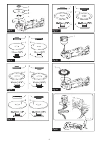
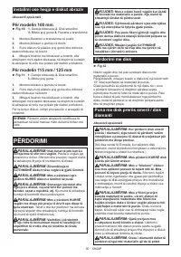
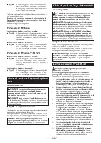
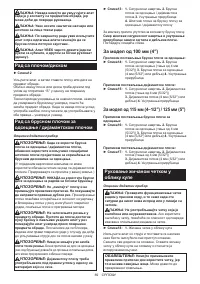
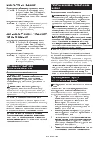
Installing or removing abrasive disc
Optional accessory
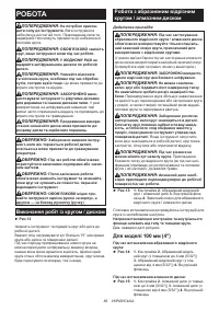
For 100 mm (4″) model
►
Fig.10:
1.
Sanding lock nut
2.
Abrasive disc
3.
Rubber pad
4.
Inner flange
1.
Mount the inner flange onto the spindle.
2.
Mount the rubber pad onto the spindle.
3.
Fit the disc on the rubber pad and screw the sand
-
ing lock nut onto the spindle.
4.
Hold the spindle with the shaft lock, and securely
tighten the sanding lock nut clockwise with the lock nut
wrench.
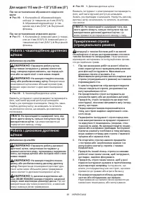
For 115 mm (4 - 1/2″) / 125 mm (5″) model
►
Fig.11:
1.
Sanding lock nut
2.
Abrasive disc
3.
Rubber pad
1.
Mount the rubber pad onto the spindle.
2.
Fit the disc on the rubber pad and screw the sand
-
ing lock nut onto the spindle.
3.
Hold the spindle with the shaft lock, and securely
tighten the sanding lock nut clockwise with the lock nut
wrench.
To remove the disc, follow the installation procedure in
reverse.
NOTE:
Use sander accessories specified in this man
-
ual. These must be purchased separately.
Содержание
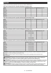
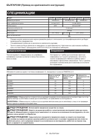
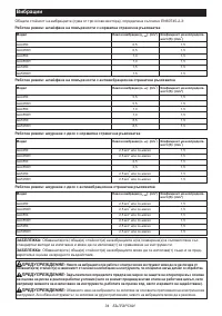
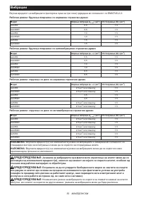
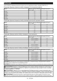
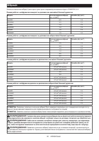
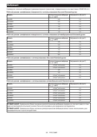
- 94 Вибрация
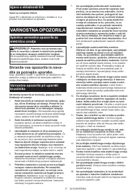
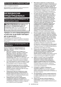
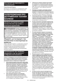
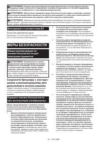
- 95 МЕРЫ БЕЗОПАСНОСТИ; Сохраните брошюру с инструк
- 98 СОХРАНИТЕ ДАННЫЕ; ОПИСАНИЕ РАБОТЫ; Фиксатор вала
- 99 СБОРКА; Установка или снятие кожуха диска; Установка и снятие гибкого диска; Установка или снятие абразивного круга
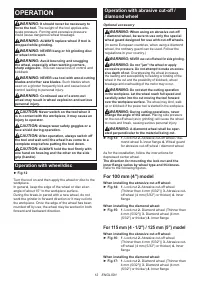
- 100 ЭКСПЛУАТАЦИЯ; Выполнение работ с диском / кругом
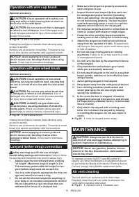
- 101 Операции с чашечной; Работа с дисковой проволочной; Подсоединение стропа
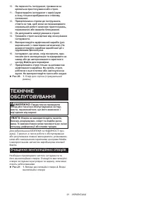
- 102 ОБСЛУЖИВАНИЕ; Очистка вентиляционного
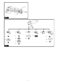
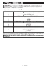
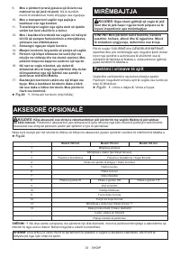
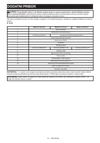
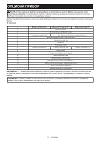
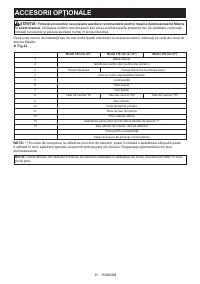
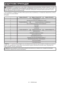
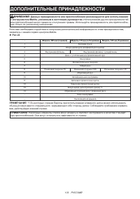
- 103 ДОПОЛНИТЕЛЬНЫЕ ПРИНАДЛЕЖНОСТИ
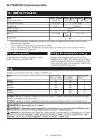
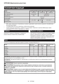
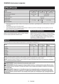
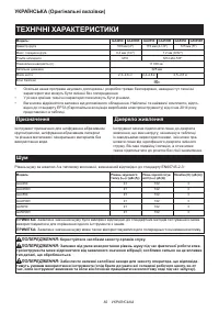
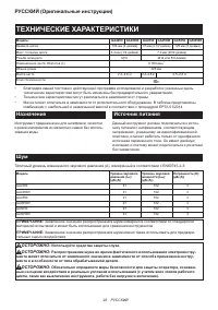
Характеристики

Остались вопросы?Не нашли свой ответ в руководстве или возникли другие проблемы? Задайте свой вопрос в форме ниже с подробным описанием вашей ситуации, чтобы другие люди и специалисты смогли дать на него ответ. Если вы знаете как решить проблему другого человека, пожалуйста, подскажите ему :)


