
Шлифмашины Makita 9565CVK - инструкция пользователя по применению, эксплуатации и установке на русском языке. Мы надеемся, она поможет вам решить возникшие у вас вопросы при эксплуатации техники.
Если остались вопросы, задайте их в комментариях после инструкции.
"Загружаем инструкцию", означает, что нужно подождать пока файл загрузится и можно будет его читать онлайн. Некоторые инструкции очень большие и время их появления зависит от вашей скорости интернета.


6
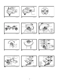
Switch action
Fig.2
For tools with the lock-on switch
CAUTION:
•
Before plugging in the tool, always check to see
that the slide switch actuates properly and returns
to the "OFF" position when the rear of the slide
switch is depressed.
To start the tool, slide the slide switch toward the "I (ON)"
position. For continuous operation, press the front of the
slide switch to lock it.
To stop the tool, press the rear of the slide switch, then
slide it toward the "O (OFF)" position.
For tools without the lock-on switch
CAUTION:
•
Before plugging in the tool, always check to see
that the slide switch actuates properly and returns
to the "OFF" position when released.
To start the tool, slide the slide switch toward the "I (ON)"
position.
To stop the tool, release the slide switch toward the "O
(OFF)" position.
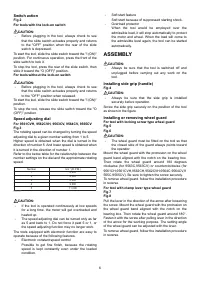
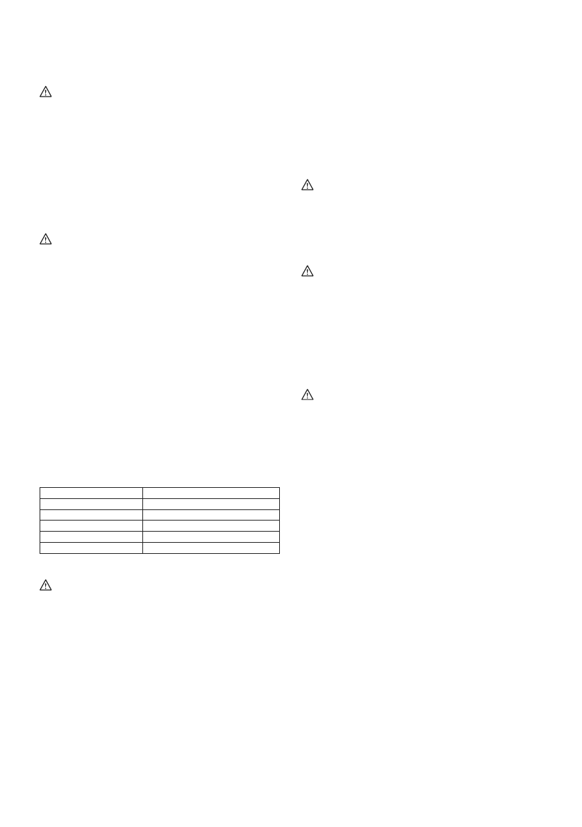
Speed adjusting dial
For 9561CVH, 9562CVH, 9563CV, 9564CV, 9565CV
Fig.3
The rotating speed can be changed by turning the speed
adjusting dial to a given number setting from 1 to 5.
Higher speed is obtained when the dial is turned in the
direction of number 5. And lower speed is obtained when
it is turned in the direction of number 1.
Refer to the below table for the relationship between the
number settings on the dial and the approximate rotating
speed.
Number
min
-
1
(R.P.M.)
1
2
,800
2
4,000
3
6
,
5
00
4
9
,000
5
11
,000
006407
CAUTION:
•
If the tool is operated continuously at low speeds
for a long time, the motor will get overloaded and
heated up.
•
The speed adjusting dial can be turned only as far
as 5 and back to 1. Do not force it past 5 or 1, or
the speed adjusting function may no longer work.
The tools equipped with electronic function are easy to
operate because of the following features.
•
Electronic constant speed control
Possible to get fine finish, because the rotating
speed is kept constantly even under the loaded
condition.
•
Soft start feature
Soft start because of suppressed starting shock.
•
Overload protector
When the tool would be employed over the
admissible load, it will stop automatically to protect
the motor and wheel. When the load will come to
the admissible level again, the tool can be started
automatically.
ASSEMBLY
CAUTION:
•
Always be sure that the tool is switched off and
unplugged before carrying out any work on the
tool.
Installing side grip (handle)
Fig.4
CAUTION:
•
Always be sure that the side grip is installed
securely before operation.
Screw the side grip securely on the position of the tool
as shown in the figure.
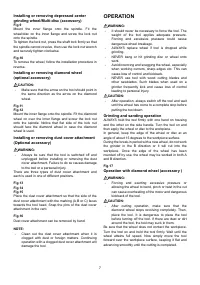
Installing or removing wheel guard
For tool with locking screw type wheel guard
Fig.5
Fig.6
CAUTION:
•
The wheel guard must be fitted on the tool so that
the closed side of the guard always points toward
the operator.
Mount the wheel guard with the protrusion on the wheel
guard band aligned with the notch on the bearing box.
Then rotate the wheel guard around 180 degrees
clockwise (for 9563C,9563CV) or counterclockwise (for
9561CH,9561CVH,9562CH,9562CVH,9564C,9564CV,9
565C,9565CV). Be sure to tighten the screw securely.
To remove wheel guard, follow the installation procedure
in reverse.
For tool with clamp lever type wheel guard
Fig.7
Fig.8
Pull the lever in the direction of the arrow after loosening
the screw. Mount the wheel guard with the protrusion on
the wheel guard band aligned with the notch on the
bearing box. Then rotate the wheel guard around 180°.
Fasten it with the screw after pulling lever in the direction
of the arrow for the working purpose. The setting angle
of the wheel guard can be adjusted with the lever.
To remove wheel guard, follow the installation procedure
in reverse.
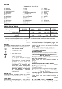
Характеристики

Остались вопросы?Не нашли свой ответ в руководстве или возникли другие проблемы? Задайте свой вопрос в форме ниже с подробным описанием вашей ситуации, чтобы другие люди и специалисты смогли дать на него ответ. Если вы знаете как решить проблему другого человека, пожалуйста, подскажите ему :)


