
Плита Bertazzoni PRO100 5I MFE D AR T - инструкция пользователя по применению, эксплуатации и установке на русском языке. Мы надеемся, она поможет вам решить возникшие у вас вопросы при эксплуатации техники.
Если остались вопросы, задайте их в комментариях после инструкции.
"Загружаем инструкцию", означает, что нужно подождать пока файл загрузится и можно будет его читать онлайн. Некоторые инструкции очень большие и время их появления зависит от вашей скорости интернета.
9
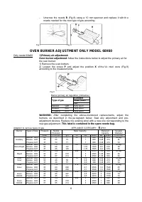
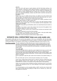
Check correct operation of the ignition system and operation of burners individually
and in combination. Burner flames should be clear blue, with no yellow tipping. If the
burners show any abnormality check that burner heads are correctly located.
Note: These burners have no aeration adjustment.
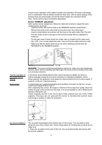
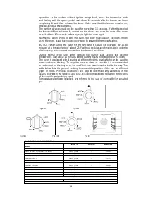
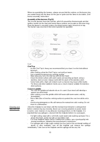
Burner "MINIMUM" adjustment
:
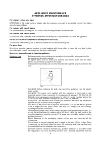
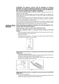
Work surface burner adjustment: follow the instructions below to adjust the work
surface burner minimum:
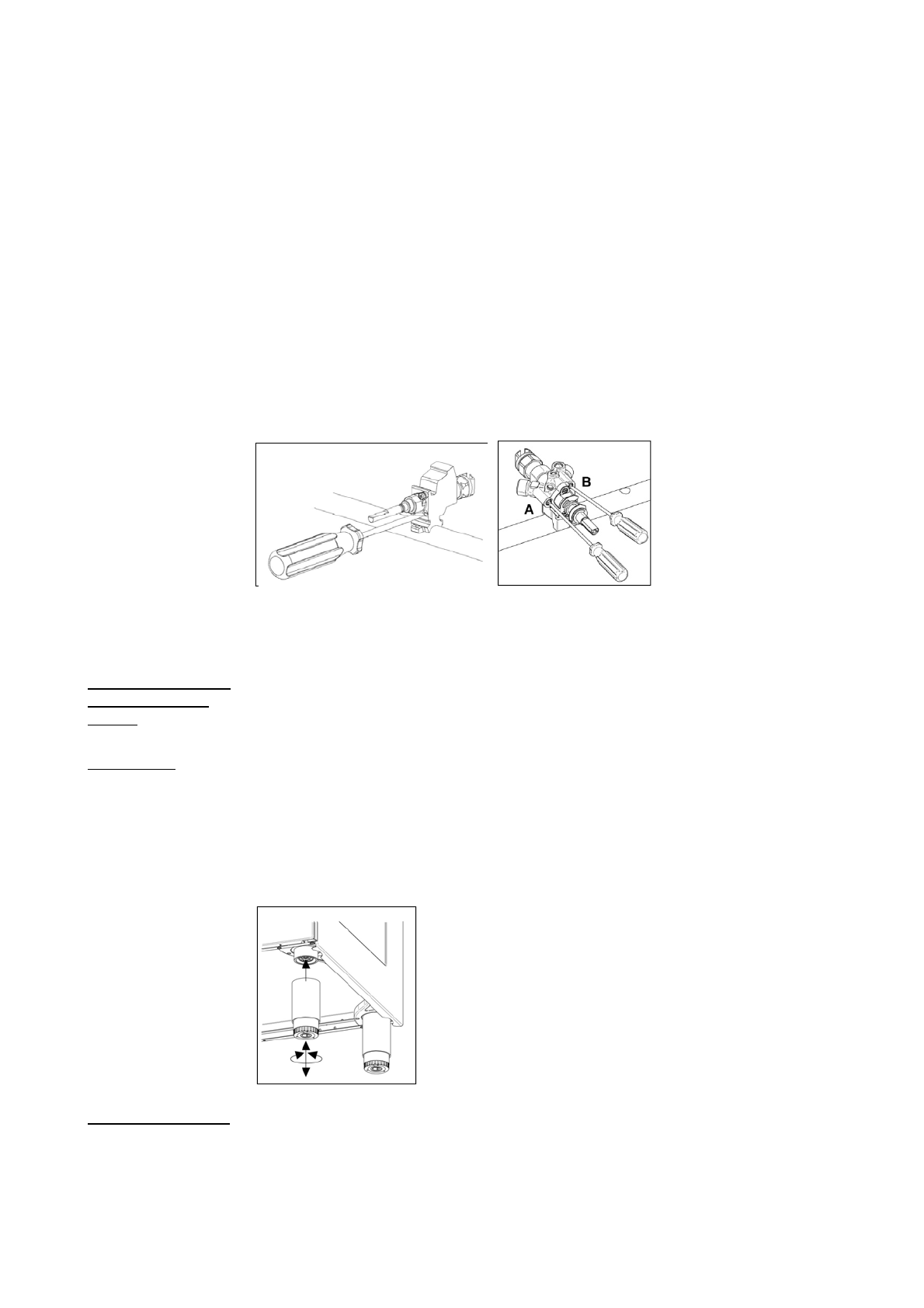
- Light the burner and set the knob to the MINIMUM position (small flame).
- Remove the knob of the valve that is press-fit on the rod of that valve.
- Insert a small slotted screwdriver into the hole on the valve body (Fig.10A) and
turn the choke screw to the right or left until the burner flame is adjusted to
minimum.
- For the gas valve of dual burner the choke valve is located on the valve body
(fig. 10B) , the A screw adjust the outer ring, the B screw adjust the inner ring.
- Make sure that the flame does not go out when switching quickly from the
MAXIMUM to the MINIMUM position.
Fig 10A
Fig 10B
WARNING:
The above-mentioned adjustment should be made only with natural gas
burners, while those o perating with liquid gas the screw must be locked at the end
in a clockwise direction.
Test the operation of It should be noted that Bertazzoni SpA cannot accept any liability for direct or
the cooker before indirect damage caused by incorrect connection or improper installation. When
leaving being repaired, the appliance must always be disconnected from the mains supply; if
required, notify our customer service.
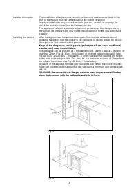
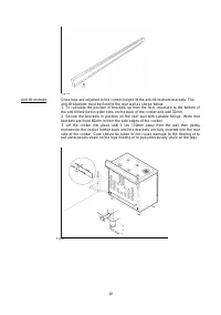
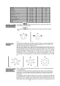
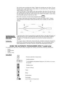
Support legs 4 support legs are supplied separately and are fitted on location to the four corners
of the lower support frame (Fig.11)
After unpacking the cooker, lift it appro x 250mm to f it the legs th en gently lower the
cooker to keep undue strain from the le gs. It is re commended to use a lifting d evice
instead of tilting the unit.
Transit supports are left in situ. Ea ch leg is fi rmly pushed over one of the t ransit
supports. If the leg s are not used and the coo ker is mounted onto a pli nth, leave
transit legs in position to allow for clearance.
Fig 11
Up-stand Installation The up-stand is packaged at the bottom rear of the cooker. The up-stand is fixed
along the rear of the cooker hob. Screw fixing points for locating the up-stand are at
either end.
1. Place the up-stand on the rear of the hob, line up locating holes and secure with
the screws supplied.
Характеристики

Остались вопросы?Не нашли свой ответ в руководстве или возникли другие проблемы? Задайте свой вопрос в форме ниже с подробным описанием вашей ситуации, чтобы другие люди и специалисты смогли дать на него ответ. Если вы знаете как решить проблему другого человека, пожалуйста, подскажите ему :)


