
Плита Bertazzoni HER96L1EAVT - инструкция пользователя по применению, эксплуатации и установке на русском языке. Мы надеемся, она поможет вам решить возникшие у вас вопросы при эксплуатации техники.
Если остались вопросы, задайте их в комментариях после инструкции.
"Загружаем инструкцию", означает, что нужно подождать пока файл загрузится и можно будет его читать онлайн. Некоторые инструкции очень большие и время их появления зависит от вашей скорости интернета.
6
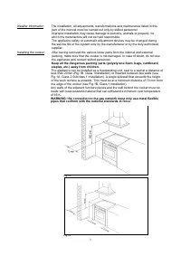
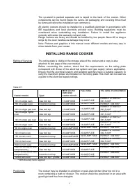
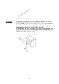
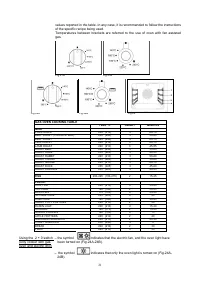
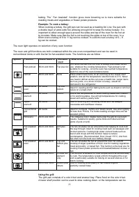
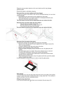
Any shelf or unit of combustible material should be at least 660mm above the
hotplate. In addition an area of 75mm wide on either side and behind the hotplate
must be clear of any combustible materials to a height of 400mm. Units must not
overhang over the hob.
Kitchen cabinets may be fitted flush to the sides of the cooker, but to allow for
cleaning and servicing
It is recommended that a 2.5mm gap be allowed on each side so that the cooker
may be moved if necessary.
The worktop or kitchen cabinets must not protrude beyond the height of the cooker
hotplate frame.
Ventilation Your appliance is not connected to a combustion products evacuation device. Th
e room in which it is to be installed must have an air supply in accordance with
national standards. The room must have an opening window or equivalent, and
some rooms may require a permanent vent in addition to the opening window.
General guidelines: The cooker must not be installed in a bedsit room of 20m³ or
less. If the cooker is installed in a room with a volume of less than 5m³, then a vent
with an effective area of 100cm³ is required. If it is installed in a room with a volume
of between 5m³ and 10m³, then an air vent with an effective area 50cm³ is
necessary. If there are other fuel burning appliances in the room, please consult
national standards for guidance.
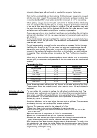
Gas connection Gas connection to the hob should be made by flexible connecting reinforced tube
.
compliant with BS 669-1. A 1/2" BSP threaded male fitting is supplied with the
cooker so that the flexible tube can be connected to the gas inlet. Appropriate
coupling connector and gas hose need to be supplied by the installer
Before connecting the appliance to the gas network, make sure that the data on the
rating plate attached on the under-oven drawer or on the back of the cooker are
compatible with what is indicated for the gas distribution network.
A rating plate attached on the last page of this handbook and in the under-oven
drawer (or on the back) of the appliance indicates the appliance adjustment
conditions: type of gas and operating pressure.
IMPORTANT: This appliance must be installed in compliance with current national
standards in force and used only in a well-ventilated room.
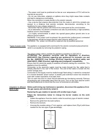
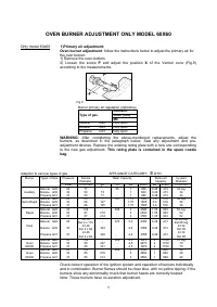
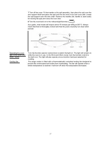
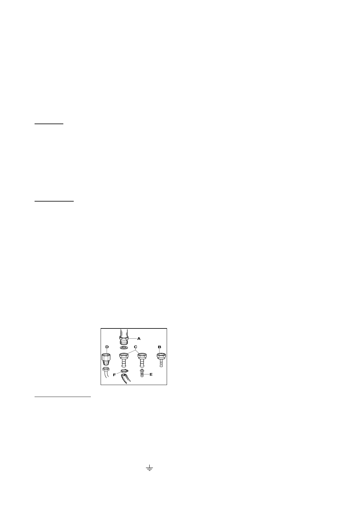
WARNING: It should be recalled that the appliance utilises a threaded 1/2" gas
cylindrical male fitting according to UNI-ISO 228-1.
To connect the appliance to the gas network with a flexible rubber hose, a
supplemental hose nipple fitting is needed (Fig.3) which is supplied with the
appliance.The appropriate coupling connector and gas hose need to be supplied by
the installer.
fig.3
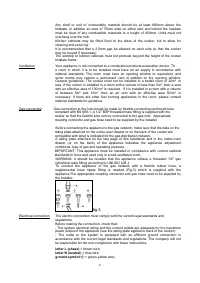
Electrical connection The electric connection must comply with the current legal standards and
regulations.
Before making the connection, check that:
- The system electrical rating and the current outlets are adequate for the maximum
power output of the appliance (see the rating plate applied to back of the cooker).
- The outlet or the system is equipped with an efficient ground connection in
accordance with the current legal standards and regulations. The company will not
be responsible for the non-compliance with these instructions.
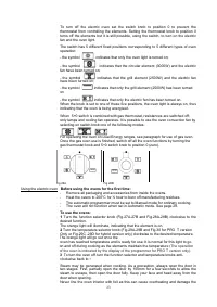
letter L (phase)
= brown wire;
letter N (neutral)
= blue wire;
ground symbol
= green-yellow wire;
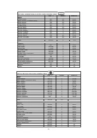
Характеристики

Остались вопросы?Не нашли свой ответ в руководстве или возникли другие проблемы? Задайте свой вопрос в форме ниже с подробным описанием вашей ситуации, чтобы другие люди и специалисты смогли дать на него ответ. Если вы знаете как решить проблему другого человека, пожалуйста, подскажите ему :)


