
Мультиметры CROWN CT44051 - инструкция пользователя по применению, эксплуатации и установке на русском языке. Мы надеемся, она поможет вам решить возникшие у вас вопросы при эксплуатации техники.
Если остались вопросы, задайте их в комментариях после инструкции.
"Загружаем инструкцию", означает, что нужно подождать пока файл загрузится и можно будет его читать онлайн. Некоторые инструкции очень большие и время их появления зависит от вашей скорости интернета.

English
11
English
12
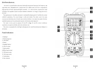
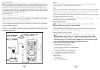
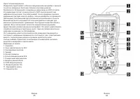
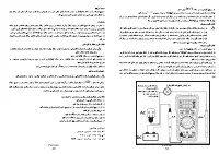
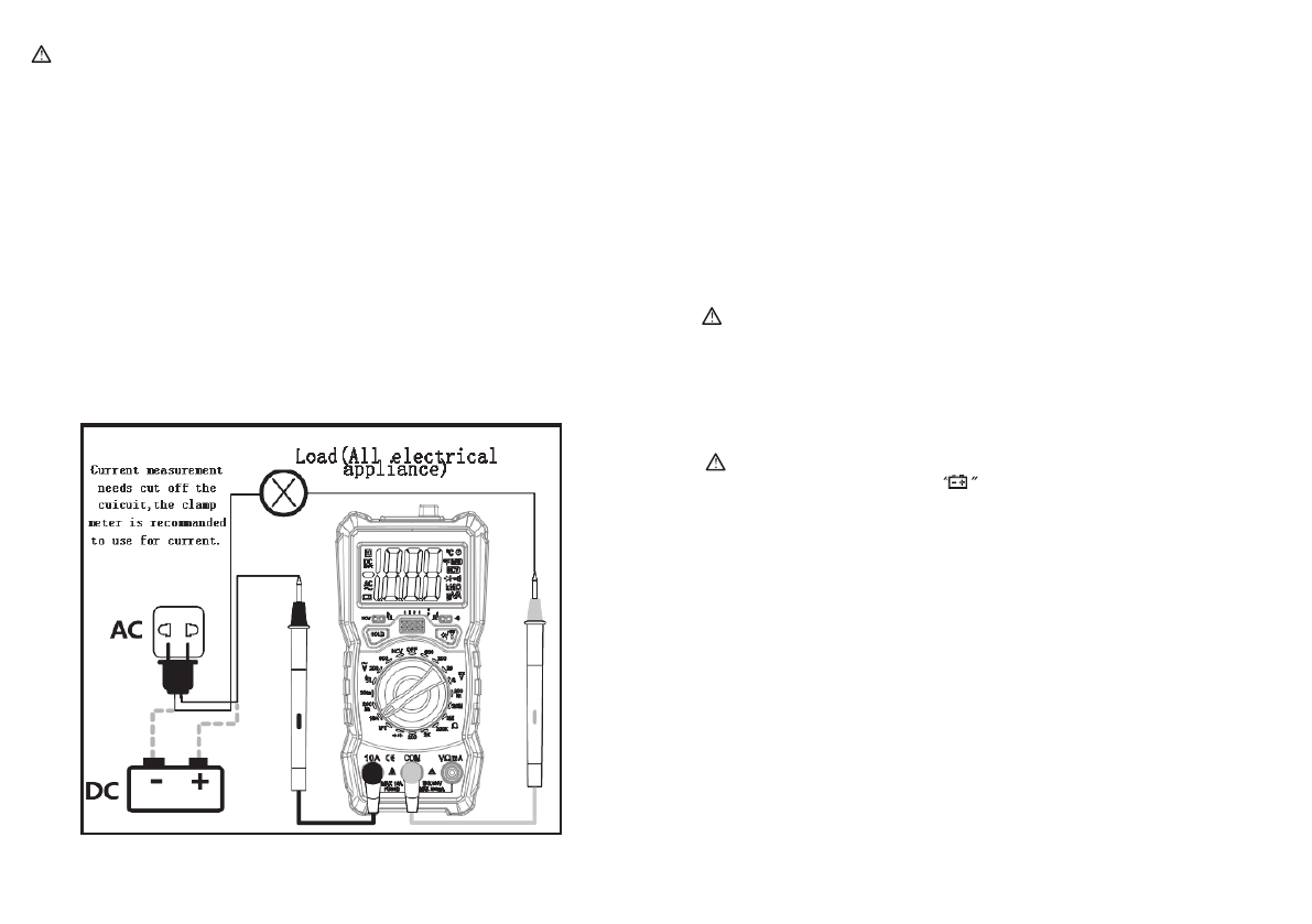
Current measurement
Do not attempt current measurement o
n the circuit when the voltage between the open
circuit voltage and ground exceeds 250 volts. If the fuse is blown during measurement, you may
damage the meter or harm yourself. To avoid damage to the meter or test equipment, use the
correct input socket, function gear, and range before making measurements before making
measurements. When the test pen is plugged into the current input socket, do not connect the
other end of the test pen in parallel to any circuit.
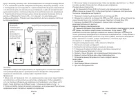
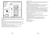
Current measurement:
1. Turn the rotary switch to mA/A.
2. Connect the black test pen to the
“
COM
”
input socket. If the measured current is less than
200mA, connect the red test pen to the
“
mA
”
input socket. If the measured current is between
200mA and10A, connect the red test lead to the
“
10A
”
input jack.
3. The circuit to be tested is disconnected, the black test pen is connected to the disconnected
circuit, the lower voltage end thereof, and the red test pen is connected to the disconnected
circuit at the higher voltage end.
4.Connect the power supply of the circuit and then read the displayed reading. If the display
shows only
“
OL
”
,this indicates that the input exceeds the selected range. The rotary switch should
be placed at a higher range.
NCV test
Notes:
1.Even if there is no indica
ti
on that the voltage may s
ti
ll exist, do not rely on non-contact voltage
detectors to determine if there is a voltage detec
ti
on opera
ti
on on the conductor, which may be
a
ff
ected by factors such as socket depth, insula
ti
on thickness, and type, etc.
2. When the input voltage is input to the instrument, due to sensing In the presence of voltage,
the voltage-sensing indicator light may light.
3. Interference sources in the external environment, such as
fla
shlights, motors, etc., may
accidentally trigger non-contact voltage detec
ti
on.
Battery and fuse replacement
Replace batteries and fuses to avoid electr
ic shock or personal injury caused by
erroneous readings. When the symbol
appears on the instrument display, replace
the battery immediately. Use only the specified fuse, instant fuse. To avoid electric shock
or personal injury, turn off the battery cover
and replace it with a new one before turning
it on. The test pen has been disconnected from the measurement circuit.
Please follow the steps below to replace the ba
tt
ery:
1.
Turn o
ff
the power of the instrument
2.
Pull all the test pens out of the input socket,
3.
Use a screwdriver to loosen the screws
fi
xing the ba
tt
ery.
4.
Remove the ba
tt
ery cover
5.
Remove the old ba
tt
ery or the damaged fuse
6.
Replace the new one Ba
tt
eries or new fuses
7.
Install ba
tt
eries cover and close the screws.
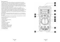
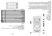
Accessories
1.
An instruc
ti
on
2.
A pair of test leads
3.
Three pieces of AAA ba
tt
eries
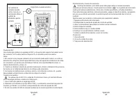
RED
BLACK
Turn the rotary switch to NCV gear and place the top of the meter close to the conductor. If
the meter detects AC voltage, the buzzer will sound an alarm.
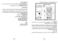
Measuring transistor
Do not apply more than 36V DC or AC voltage to the common terminal and hFE
terminal to prevent electric shock or instrument damage.
1. Turn the rotary switch to hFE gear
2. Determine whether the transistor is NPN or PNP type, and then insert the three legs of the
transistor e.b.c into the corresponding holes of hFE test base.
3. The hFE similarity value of the tested transistor is read from the liquid crystal display.


