
Мультиметры CROWN CT44051 - инструкция пользователя по применению, эксплуатации и установке на русском языке. Мы надеемся, она поможет вам решить возникшие у вас вопросы при эксплуатации техники.
Если остались вопросы, задайте их в комментариях после инструкции.
"Загружаем инструкцию", означает, что нужно подождать пока файл загрузится и можно будет его читать онлайн. Некоторые инструкции очень большие и время их появления зависит от вашей скорости интернета.

English
9
English
10
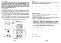
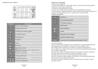
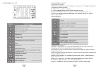
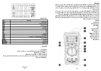
2. Long press
to turn on the illumina
ti
on func
ti
on and the backlight at the same
ti
me. Short
press the key again to turn o
ff
the illumina
ti
on func
ti
on. It turns o
ff
automa
ti
cally with no
opera
ti
on for 30S.
Auto power off
A
ft
er about 15 minutes a
ft
er power on, if there is no opera
ti
ng instrument, it will give audible
voice prompts, will automa
ti
cally cut o
ff
the power, enter the hiberna
ti
on mode, in the automa
ti
c
shutdown mode, any key can be restarted.
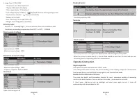
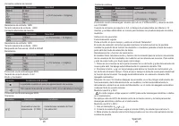
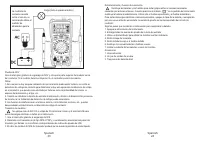
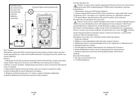
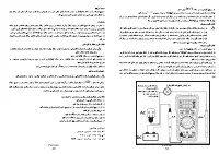
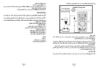
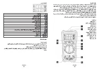
ACV and DCV measurement
Do not measure any voltage greater than 600V to prevent electric shock or damage to the
instrument.
Do not apply more than 600V voltage between the common and earth to prevent electric
shock or damage to the instrument.
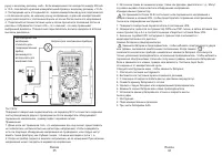
ACV or DCV measuring:
1. Turn the switch to
or
.
2. Connect the black test pen to the COM jack and the red pen to the V jack.
3. Measure the voltage value of the circuit under test with the other two ends of the test pens.
4. The reading will be shown on the LED display as well as the polarity of the end connected with
the red lead.
Notes:
*The meter shows readings in range DCV 200mV and 2V even there is no input voltage or test
pens connec
ti
on. Then short circuit
and
“
COM
”
to make the meter shows zero.
*Please change to a higher range if the “OL” is shown .
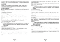
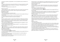
Resistance measurement
To avoid damage to the meter or device under test, all power to the circuit under test
should be cut off before measuring resistance, and all high
-
voltage capacitors should
be fully discharged.
Resistor measuring:
1. Rotate the rotary switch to the proper posi
ti
on.
2. Connect the black test pen and the red test pen to the
“
COM
”
input socket and
input
socket 3.Uses the test pen to test the resistance value of the circuit.
4. The resistance value shows on the display window .
Notes:
*The resistance value measured on the circuit is usually di
ff
erent from the resistance ra
ti
ng.
*
To measure the low resistance accurately, please short-circuit the two test pens to read out the
short-circuit resistance of the test leads, and subtract it by the readings to get accurate resistance
value.
*At 20megohms range, the reading will stabilize a
ft
er a few seconds, which is normal for high
resistance measurements.
*When the meter is not in circuit, the display will show
“
OL
”
, indica
ti
ng that the measurement
value is out of the measurement range.
Diode measurement
To avoid damage to the meter or device under test, all power to the circuit under test
should be cut off before measuring diode, and all high
-
voltage capacitors should be fully
discharged.
Test a diode outside the circuit.
:
1. Turn the rotary switch to
posi
ti
on.
2. Connect the black test pen and the red test pen to the
“
COM
”
input socket and “ V/
Ω”
input
socket
3. Connect the black test pen and red test pen to the nega
ti
ve and posi
ti
ve electrodes of the
diode under test.
4. The meter will display the forward bias value of the diode under test. If the polarity is reversed,
then it shows
‘
OL
’
.
The normal diode in the circuit s
ti
ll produces a forward voltage drop of 0.5V to 0.8V, but the
reverse bias reading will depend on the variety of the resistance value of the other channels
between the two test pens.
Buzzer test
To avoid damage to the meter or device under test, all power to the circuit under test
should be cut off before measuring on
-
off of the circuit and all high
-
voltage capacitors
should be fully discharged.
For on-off state of the circuit:
1. Turn the rotary switch to
posi
ti
on.
2. Connect the black test pen and the red test pen to the
“
COM
”
input socket and
input
socket
3. Measure the resistance of the circuit under test at the other end of the test pens. If the
resistance of the circuit under test is not greater than about 30 ohms, the indicator light will turn
on and the buzzer will sound con
ti
nuously.


