
Мойки высокого давления Stiga HPS 235 R 2C1351801/ST1 - инструкция пользователя по применению, эксплуатации и установке на русском языке. Мы надеемся, она поможет вам решить возникшие у вас вопросы при эксплуатации техники.
Если остались вопросы, задайте их в комментариях после инструкции.
"Загружаем инструкцию", означает, что нужно подождать пока файл загрузится и можно будет его читать онлайн. Некоторые инструкции очень большие и время их появления зависит от вашей скорости интернета.


78
English
EN
4
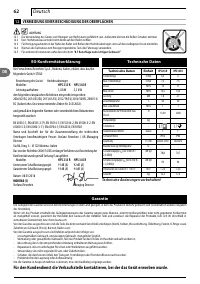
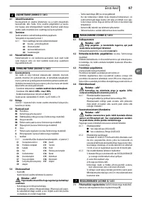
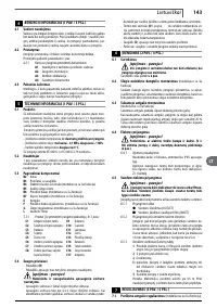
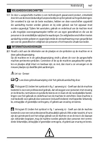
GENERAL INFORMATION (FIG.1)/PAGE 3
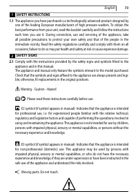
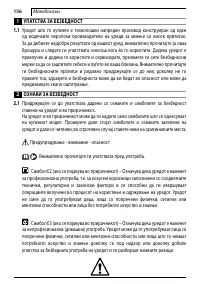
4.1 Use of the manual
The manual forms an integral part of the appliance and should be
kept for future reference. Please read it carefully before installing/
using the unit. If the appliance is sold, the seller must pass on this
manual to the new owner along with the appliance.
4.2 Delivery
The appliance is delivered partially assembled in a cardboard box.
The supply package is illustrated in fig.1.
4.2.1
Documentation supplied with the appliance
A1 Use and maintenance manual
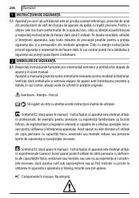
A2 Safety instructions
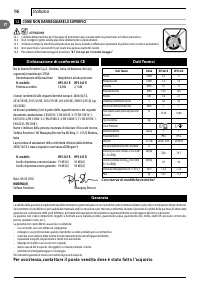
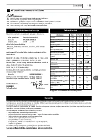
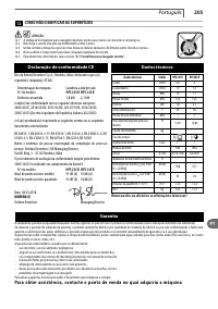
A3 Declaration of conformity
A4 Warranty regulations
4.3 Disposing of packaging
The packaging materials are not environmental pollutants but must
still be recycled or disposed of in compliance with the relevant
legislation in the country of use.
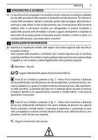
5
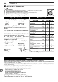
TECHNICAL INFORMATION (FIG.1)/PAGE 3
5.1 Envisaged use
This appliance has been designed for individual use for the cleaning
of vehicles, machines, boats, masonry, etc., to remove stubborn dirt
using clean water and biodegradable chemical detergents.
Vehicle engines may be washed only if the dirty water is disposed of
as per regulations in force.
- Intake water temperature: see data plate on the appliance.
- Intake water pressure: min. 0.1 MPa - max. 1 MPa.
- Operating ambient temperature: above 0°C.
The appliance is compliant with the IEC 60335-1 and IEC 60335-2-79
standards.
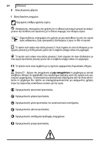
5.2 Operator
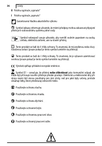
The symbol illustrated in fig. 1 identifies the appliance’s intended
operator (professional or non-professional).
5.3 Main components
B2 Lance
B3 Gun with safety catch
B4 Electric cable with plug (on models with this feature)
B5 High pressure hose
B6 Detergent tank (on models with this feature)
B7 Oil cap (on models with this feature)
E
Nozzle
F
Detergent regulator (on models with this feature)
G Pressure regulator (on models with this feature)
L
Water filter
5.3.1
Accessories (if included in the supply package – see fig.1)
C1
Nozzle cleaning tool
C2
Rotating nozzle kit
C3
Handle
C4
Brush
C5
Hose reel
C6
Water suction kit
C7
Pipe jet kit
C8
Large surface
cleaning brush kit
C9
Adapter
C10
Screws
C11
Brackets
C12
Lever
C13
Detergent kit
C14
Wheels
C15
Lubricating grease tube
C16
Pressure gauge
C17
Accessories adapter
5.4
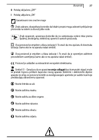
Safety devices
- Starter device (H)
The starter device prevents accidental use of the appliance.
Warning - danger!
Do not tamper with or adjust the safety valve setting.
- Safety valve and/or pressure limiting valve.
The safety valve is also a pressure limiting valve. When the gun
trigger is released, the valve opens and the water recirculates
through the pump inlet or is discharged onto the ground.
- Thermostat valve (D1 where fitted) If the water temperature
exceeds the temperature set by the manufacturer, the thermostat
valve discharges the hot water and draws in an amount of cold
water equal to the amount of water discharged, until the correct
temperature is restored.
- Safety catch (D): prevents accidental spraying of water.
- Overload cutout: stops the appliance in case of overload.
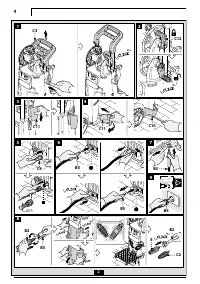
6
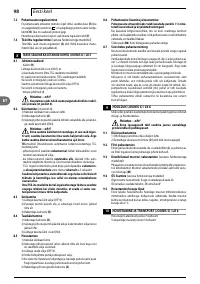
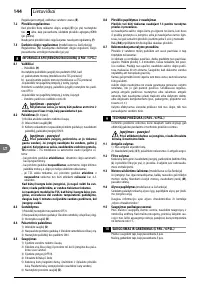
INSTALLATION (FIG.2)/PAGE 4
6.1 Assembly
Warning - danger!
All installation and assembly operations must be per-
formed with the appliance disconnected from the mains power
supply.
The assembly sequence is illustrated in fig.2.
6.2 Fitting the pressure release caps
(on models with this feature)
To prevent oil leaks, the appliance is delivered with the oil intakes
sealed with red caps which must be replaced with the pressure
release caps supplied.
6.3 Fitting the rotating nozzle
(For models with this feature).
The rotating nozzle kit delivers greater washing power.
Use of the rotating nozzle may cause a reduction in pressure of
25% compared to the pressure obtained with the adjustable nozzle.
However, the rotating nozzle kit delivers greater washing power due
to the rotation of the water jet.
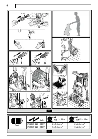
6.4 Electrical connection
Warning - danger!
Check that the electrical supply voltage and frequency
(V-Hz) correspond to those specified on the data plate (fig.2).
6.4.1
Use of extension cables
Use cables and plugs with "IPX5" protection level.
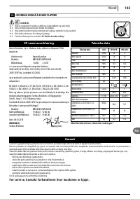
The cross-section of the extension cable should be pro-
portionate to its length; the longer it is, the greater its
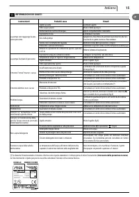
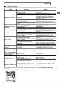
cross-section should be. See table 1.
6.5 Water supply connection
Warning - danger!
Only clean or filtered water should be supplied to
the appliance. The flow rate of the water inlet tap should be
equal to the pump flow rate.
Place the appliance as close to the water supply system as possible.
6.5.1
Connection points
l
Water outlet (OUTLET)
n
Water inlet with filter (INLET)
6.5.2
Connection to the mains water supply
The appliance may only be connected directly to the
mains drinking water supply if the supply hose is fitted
with a backflow preventer valve as per current regulations
in force. Make sure that the hose is at least Ø 13 mm, that
it is reinforced and that it is not more than 25 m long.
6.5.3
Suction of water from open containers
1) Screw the inlet hose with filter to the water INLET and
insert it down to the bottom of the container.
2) Vent the air from the appliance:
a) Unscrew the lance.
b) Start the appliance and keep the gun open until there
are no air bubbles in the water flowing out.
3) Switch the appliance off and screw the lance back on.
N.B.: the maximum suction height is 0.5 m. The suction
hose should be filled before use.
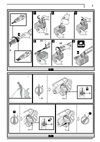
7
ADJUSTMENTS (FIG.3)/PAGE 5
7.1 Adjusting the spray nozzle (for models with this feature)
Water flow is adjusted by regulating the nozzle (E).


