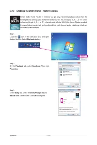
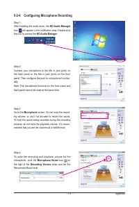
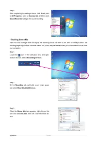
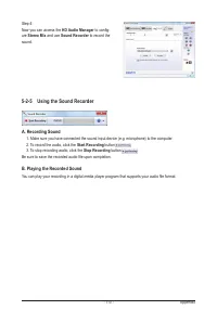
Материнские платы GIGABYTE GA P67A UD7 rev 1 0 - инструкция пользователя по применению, эксплуатации и установке на русском языке. Мы надеемся, она поможет вам решить возникшие у вас вопросы при эксплуатации техники.
Если остались вопросы, задайте их в комментариях после инструкции.
"Загружаем инструкцию", означает, что нужно подождать пока файл загрузится и можно будет его читать онлайн. Некоторые инструкции очень большие и время их появления зависит от вашей скорости интернета.


- 32 -
Hardware Installation
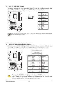
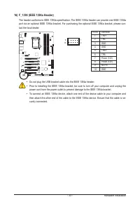
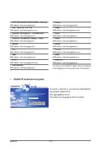
14) F_USB1/F_USB2 (USB Headers)
The headers conform to USB 2.0/1.1 specification. Each USB header can provide two USB ports via an
optional USB bracket. For purchasing the optional USB bracket, please contact the local dealer.
10
9
2
1
Pin No. Definition
1
Power (5V)
2
Power (5V)
3
USB DX-
4
USB DY-
5
USB DX+
6
USB DY+
7
GND
8
GND
9
No Pin
10
NC
•
Do not plug the IEEE 1394 bracket (2x5-pin) cable into the USB 2.0/1.1 header.
•
Prior to installing the USB bracket, be sure to turn off your computer and unplug the power
cord from the power outlet to prevent damage to the USB bracket.
When the system is in S4/S5 mode, only the USB ports routed to the F_USB1 header can sup-
port the ON/OFF Charge function.
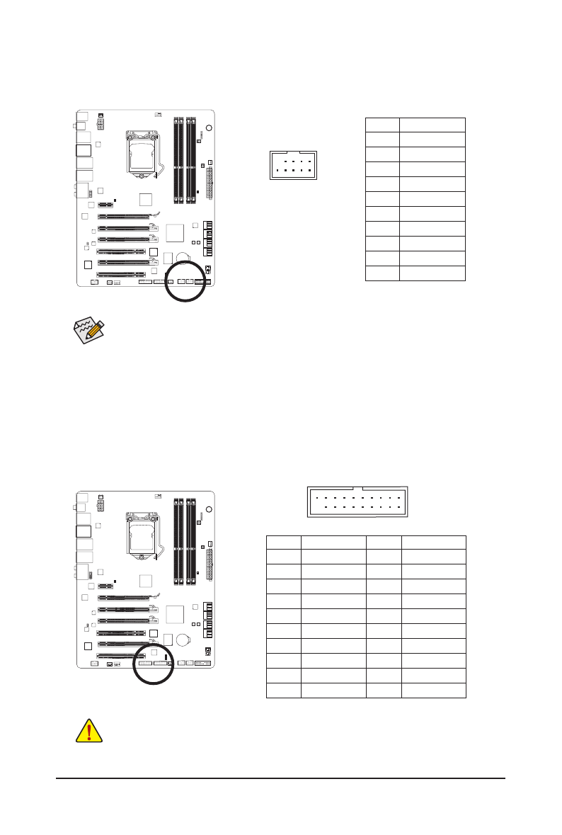
15) F_USB30_1/F_USB30_2 (USB 3.0/2.0 Headers)
The headers conform to USB 3.0/2.0 specification. Each USB header can provide two USB ports via an
optional USB bracket. For purchasing the optional USB bracket, please contact the local dealer.
F_USB30
F_AUDIO(H)
DB_PORT
10
11
20
1
Pin No. Definition
11
D2+
12
D2-
13
GND
14
SSTX2+
15
SSTX2-
16
GND
17
SSRX2+
18
SSRX2-
19
VBUS
20
No Pin
Pin No. Definition
1
VBUS
2
SSRX1-
3
SSRX1+
4
GND
5
SSTX1-
6
SSTX1+
7
GND
8
D1-
9
D1+
10
NC


