Материнские платы GIGABYTE GA H67MA D2H B3 rev 1 1 - инструкция пользователя по применению, эксплуатации и установке на русском языке. Мы надеемся, она поможет вам решить возникшие у вас вопросы при эксплуатации техники.
Если остались вопросы, задайте их в комментариях после инструкции.
"Загружаем инструкцию", означает, что нужно подождать пока файл загрузится и можно будет его читать онлайн. Некоторые инструкции очень большие и время их появления зависит от вашей скорости интернета.


- 23 -
Hardware Installation
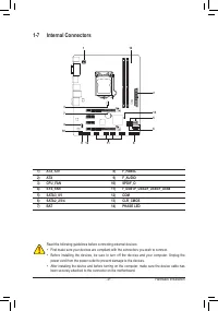
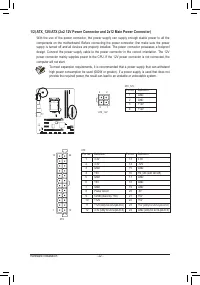
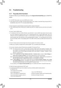
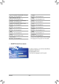
3/4) CPU_FAN/SYS_FAN (Fan Headers)
The motherboard has a 4-pin CPU fan header (CPU_FAN) and a 4-pin (SYS_FAN) system fan. Most fan
headers possess a foolproof insertion design. When connecting a fan cable, be sure to connect it in the
correct orientation (the black connector wire is the ground wire). The motherboard supports CPU fan
speed control, which requires the use of a CPU fan with fan speed control design. For optimum heat dis-
sipation, it is recommended that a system fan be installed inside the chassis.
•
Be sure to connect fan cables to the fan headers to prevent your CPU and system from over-
heating. Overheating may result in damage to the CPU or the system may hang.
•
These fan headers are not configuration jumper blocks. Do not place a jumper cap on the headers.
CPU_FAN:
Pin No. Definition
1
GND
2
+12V / Speed Control
3
Sense
4
Speed Control
SYS_FAN:
Pin No. Definition
1
GND
2
+12V / Speed Control
3
Sense
4
Reserve
SYS_FAN
CPU_FAN
DEBUG
PORT
G.QBOFM
1
DEBUG
PORT
G.QBOFM
1
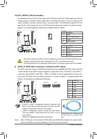
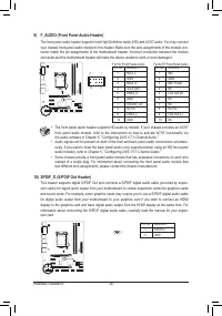
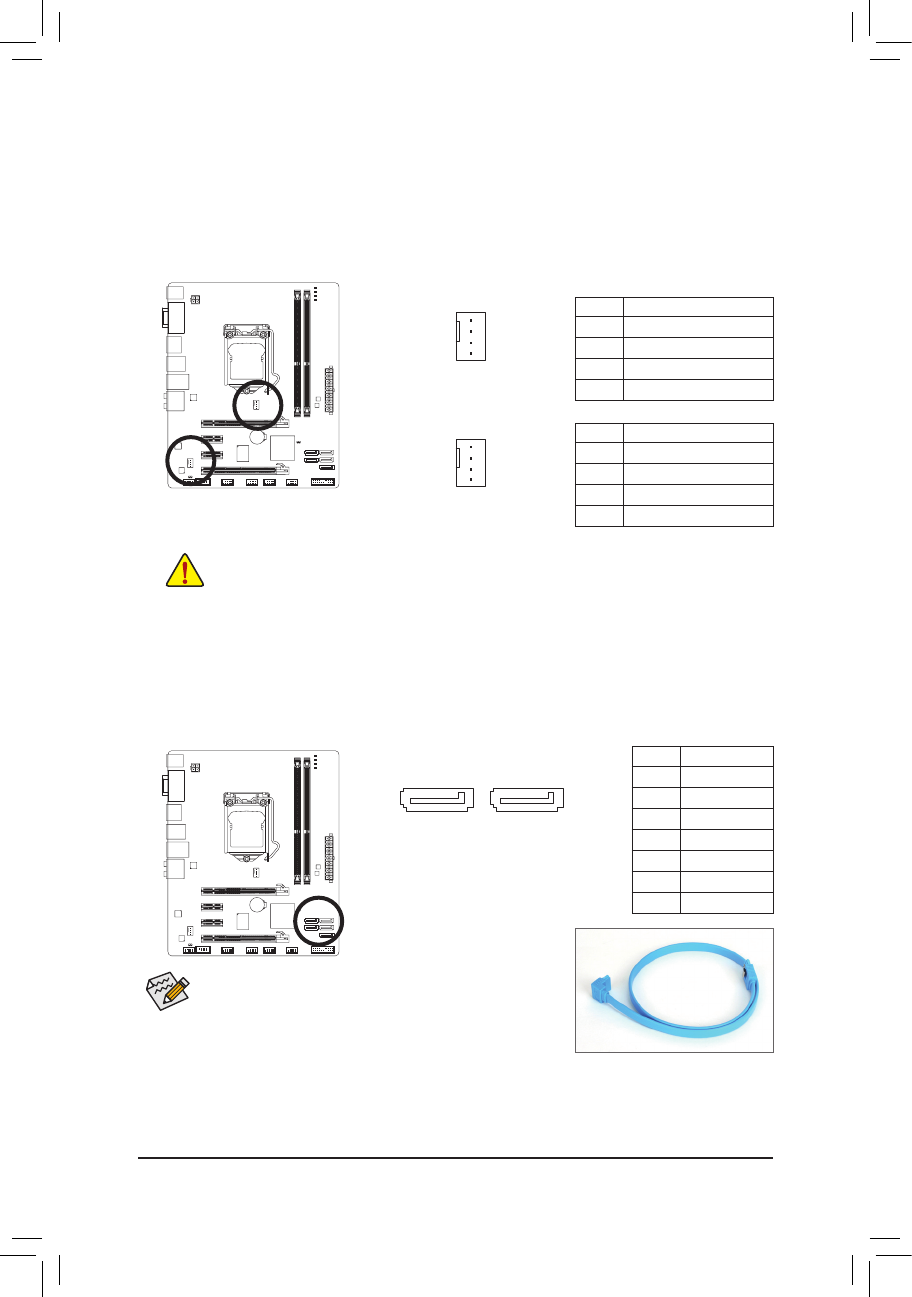
5) SATA3_0/1 (SATA 6Gb/s Connectors, Controlled by H67 Chipset)
The SATA connectors conform to SATA 6Gb/s standard and are compatible with SATA 3Gb/s and SATA
1.5Gb/s standard. Each SATA connector supports a single SATA device. The SATA3_0 and SATA3_1
connectors support RAID 0 and RAID 1. RAID 5 and RAID 10 can be implemented on the two con-
nectors with the SATA2_2/3/4 and eSATA connectors
(Note)
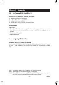
. Refer to Chapter 5, "Configuring SATA Hard
Drive(s)," for instructions on configuring a RAID array.
Pin No. Definition
1
GND
2
TXP
3
TXN
4
GND
5
RXN
6
RXP
7
GND
DEBUG
PORT
G.QBOFM
DEBUG
PORT
G.QBOFM
SATA3_0
SATA3_1
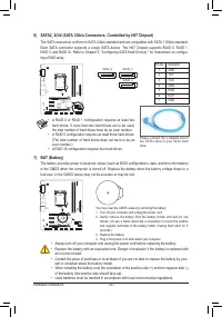
•
A RAID 0 or RAID 1 configuration requires at least two hard
drives. If more than two hard drives are to be used, the total
number of hard drives must be an even number.
•
A RAID 5 configuration requires at least three hard drives.
(The total number of hard drives does not have to be an
even number.)
•
A RAID 10 configuration requires four hard drives.
Please connect the L-shaped end of
the SATA cable to your SATA hard
drive.
(Note) When a RAID set is built across the SATA 6Gb/s and SATA 3Gb/s channels, the system perfor-
mance of the RAID set may vary depending on the devices being connected.
1
7


