Материнские платы GIGABYTE GA H55M S2H rev 1 0 - инструкция пользователя по применению, эксплуатации и установке на русском языке. Мы надеемся, она поможет вам решить возникшие у вас вопросы при эксплуатации техники.
Если остались вопросы, задайте их в комментариях после инструкции.
"Загружаем инструкцию", означает, что нужно подождать пока файл загрузится и можно будет его читать онлайн. Некоторые инструкции очень большие и время их появления зависит от вашей скорости интернета.


- 20 -
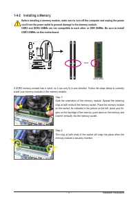
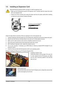
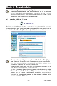
Hardware Installation
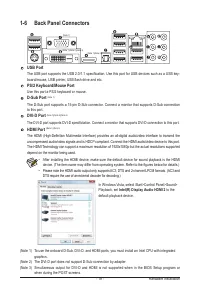
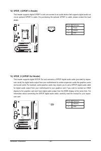
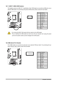
Optical S/PDIF Out Connector
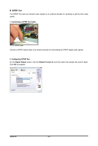
This connector provides digital audio out to an external audio system that supports digital optical audio.
Before using this feature, ensure that your audio system provides an optical digital audio in connector.
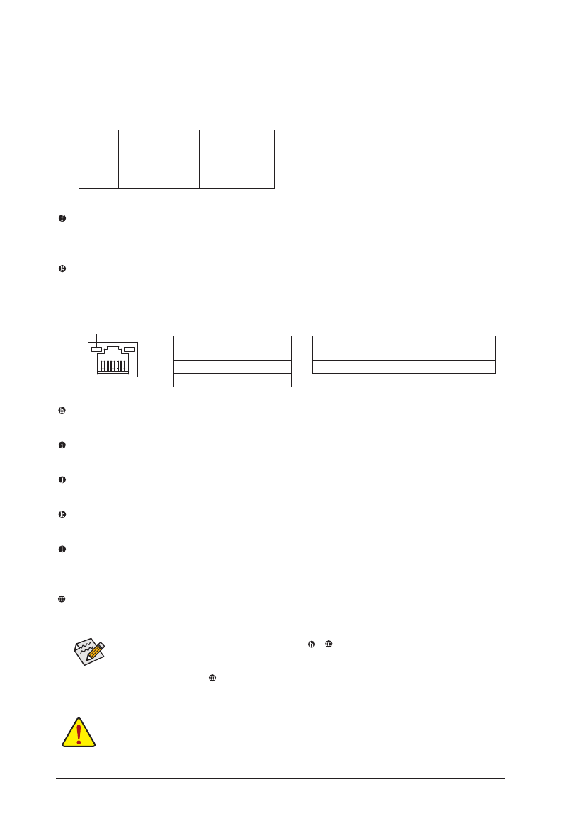
RJ-45 LAN Port
The Gigabit Ethernet LAN port provides Internet connection at up to 1 Gbps data rate. The following de-
scribes the states of the LAN port LEDs.
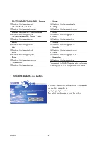
Dual Display Configurations for the Onboard Graphics:
The table below shows
the supported dual display configurations for the onboard graphics ports when
in the BIOS Setup program or when during the POST stage. There is no such limitation in operating sys-
tem environment.
Combination Supported or Not
DVI-D + D-Sub
Yes
DVI-D + HDMI
No
HDMI + D-Sub
Yes
Display
Matrix
Activity LED:
State
Description
Blinking Data transmission or receiving is occurring
Off
No data transmission or receiving is occurring
Connection/Speed LED:
State
Description
Orange
1 Gbps data rate
Green
100 Mbps data rate
Off
10 Mbps data rate
Activity LED
Connection/
Speed LED
LAN Port
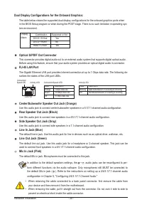
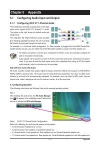
Center/Subwoofer Speaker Out Jack (Orange)
Use this audio jack to connect center/subwoofer speakers in a 5.1/7.1-channel audio configuration.
Rear Speaker Out Jack (Black)
Use this audio jack to connect rear speakers in a 4/5.1/7.1-channel audio configuration.
Side Speaker Out Jack (Gray)
Use this audio jack to connect side speakers in a 7.1-channel audio configuration.
Line In Jack (Blue)
The default line in jack. Use this audio jack for line in devices such as an optical drive, walkman, etc.
Line Out Jack (Green)
The default line out jack. Use this audio jack for a headphone or 2-channel speaker. This jack can be
used to connect front speakers in a 4/5.1/7.1-channel audio configuration.
Mic In Jack (Pink)
The default Mic in jack. Microphones must be connected to this jack.
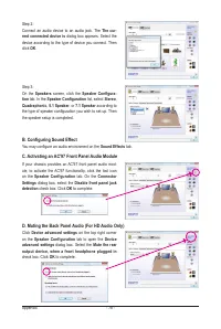
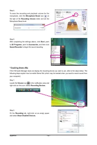
In addition to the default speakers settings, the ~
audio jacks can be reconfigured to per
-
form different functions via the audio software. Only microphones still MUST be connected to
the default Mic in jack ( ). Refer to the instructions on setting up a 2/4/5.1/7.1-channel audio
configuration in Chapter 5, "Configuring 2/4/5.1/7.1-Channel Audio."
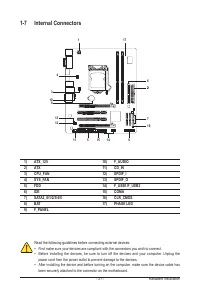
•
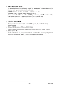
When removing the cable connected to a back panel connector, first remove the cable from
your device and then remove it from the motherboard.
•
When removing the cable, pull it straight out from the connector. Do not rock it side to side to
prevent an electrical short inside the cable connector.


