Материнские платы GIGABYTE GA H55 USB3 rev 2 0 - инструкция пользователя по применению, эксплуатации и установке на русском языке. Мы надеемся, она поможет вам решить возникшие у вас вопросы при эксплуатации техники.
Если остались вопросы, задайте их в комментариях после инструкции.
"Загружаем инструкцию", означает, что нужно подождать пока файл загрузится и можно будет его читать онлайн. Некоторые инструкции очень большие и время их появления зависит от вашей скорости интернета.

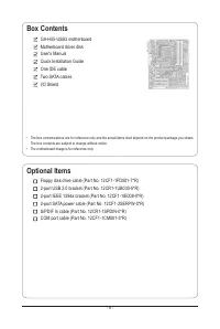


Hardware Installation
- 24 -
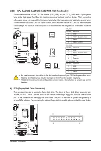
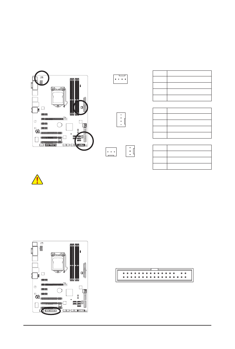
3/4/5) CPU_FAN/SYS_FAN1/SYS_FAN2/PWR_FAN (Fan Headers)
The motherboard has a 4-pin CPU fan header (CPU_FAN), a 4-pin (SYS_FAN2) and a 3-pin system
fans, and a 3-pin power fan. Most fan headers possess a foolproof insertion design. When connecting
a fan cable, be sure to connect it in the correct orientation (the black connector wire is the ground wire).
The motherboard supports CPU fan speed control, which requires the use of a CPU fan with fan speed
control design. For optimum heat dissipation, it is recommended that a system fan be installed inside the
chassis.
•
Be sure to connect fan cables to the fan headers to prevent your CPU and system from over-
heating. Overheating may result in damage to the CPU or the system may hang.
•
These fan headers are not configuration jumper blocks. Do not place a jumper cap on the
headers.
CPU_FAN:
Pin No. Definition
1
GND
2
+12V / Speed Control
3
Sense
4
Speed Control
SYS_FAN2:
Pin No. Definition
1
GND
2
+12V / Speed Control
3
Sense
4
Reserve
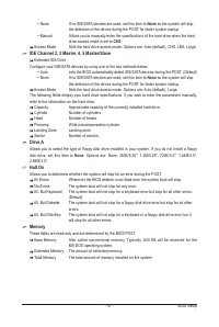
6) FDD (Floppy Disk Drive Connector)
This connector is used to connect a floppy disk drive. The types of floppy disk drives supported are:
360 KB, 720 KB, 1.2 MB, 1.44 MB, and 2.88 MB. Before connecting a floppy disk drive, be sure to locate
pin 1 of the connector and the floppy disk drive cable. The pin 1 of the cable is typically designated by a
stripe of different color. For purchasing the optional floppy disk drive cable, please contact the local dealer.
SYS_FAN2
CPU_FAN
DEBUG
PORT
G.QBOFM
DEBUG
PORT
G.QBOFM
1
1
2
1
1
1
SYS_FAN1/PWR_FAN:
Pin No. Definition
1
GND
2
+12V
3
Sense
SYS_FAN1
PWR_FAN
34
33


