Материнские платы GIGABYTE GA 8I915P Pro rev 1 x - инструкция пользователя по применению, эксплуатации и установке на русском языке. Мы надеемся, она поможет вам решить возникшие у вас вопросы при эксплуатации техники.
Если остались вопросы, задайте их в комментариях после инструкции.
"Загружаем инструкцию", означает, что нужно подождать пока файл загрузится и можно будет его читать онлайн. Некоторые инструкции очень большие и время их появления зависит от вашей скорости интернета.


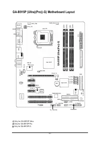
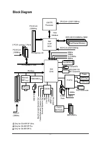


GA- 8I915P Series M o therbo ard
- 12 -
English
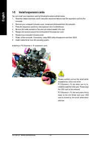
1-3
Installation of the CPU and Heatsink
Befor e installing the CPU, plea se com ply with the following conditions:
1. Please m ake su re that the m otherboard sup ports the CPU.
2. Please tak e note of the one indented corner of the CPU. If you install the CPU in the wrong
direction, the CPU will not insert properly. If this occurs, please change the insert direction
of the CPU.
3. Please add an even layer of hea t sink paste between the CPU and hea tsink.
4. Please m a ke sure the heatsink is installed on the CPU prior to system use, otherwise
overheating and perm anent dam age of the CPU m ay occur.
5. Please set the CPU host frequency in accordance with the processor specifications. It is not
recom m ended that the system bus frequency be set beyond hardware specifications since it
does no t m eet the re quired standa rds for the p eripherals. If you wish to set the fr equency
beyond the prop er specifications, please do so according to your hardware specifications
including the CPU, graphics card, m em ory, hard drive, etc.
HT functionality requirement content :
Enabling the functionality of Hyper-Threading Technology for your com p uter system requires all
of the following platform com po nents:
- CPU: An In tel
®
Pentiu m 4 Processor with HT Tec hnology
- Chipset: An Intel
®
Chips et that supp orts HT Tech nology
- BIOS: A BIOS that suppor ts HT Tech nology and has it en abled
- OS: An op eration system that ha s optim izations for HT Technology
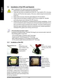
1-3-1 Installation of the CPU
Fig. 1
Gently lift the m etal
le v er lo c ate d o n th e
CPU socke t to the
uprig ht position.
M etal Lever
Fig. 2
Re m o v e th e p l a s tic
c ov er in g o n th e CPU
socket.
F ig . 3
No tice the sm all go ld
colored trian gle
loc ated on the edge of
the CPU so ck et.
Align the inden ted
cor ner o f the CPU with
Fig. 4
Once the CPU is
properly inserted,
please re place the
plastic co vering and
push the m etal lever
back into its orig inal
position.
the tria ngle and gently ins ert the CPU in to p osition.
( Gr a s pin g th e CPU fir m ly b etwee n yo u r th um b
and forefinger , car efully plac e it into the so cket in a
stra ig ht an d downwar ds m o tio n. Avoid twistin g or
be nding m o tio ns tha t m ig ht cau se dam ag e to the
CPU du rin g in sta lla tion .)


